
Three Phase Matrix-DAB Converter
Description of the Three Phase Matrix-DAB Converter component in Schematic Editor.
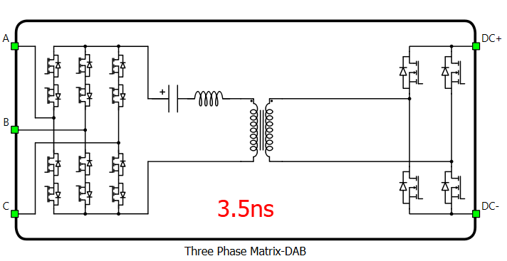
Schematic Block Diagram
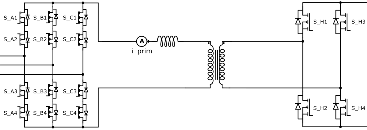
The Three Phase Matrix-DAB Converter simulates a converter topology similar to a Dual Active Bridge, in which the AC-side bridge is a three-phase matrix converter built using anti-series MOSFETs as four-quadrant switches. The matrix bridge uses twelve switches, four for each of the three AC phases (A, B, and C), and connects to the AC grid through a transformer. The DC side is a full H-bridge built from four switches. Filter capacitors shall be connected to the AC-side inputs of the component.
In real-time simulation, this converter block uses the dedicated UltraCore FPGA hardware resource in order to achieve a reduced simulation step for this topology. UltraCore weight of the Three Phase Matrix-DAB Converter is 3.
Control
Gate drive inputs can be assigned to any of the digital input pins (from 1 to 32(64)). For example, if S_A1 is assigned to 1, the digital input pin 1 will be routed to the S_A1 switch gate drive. In addition, the *_logic parameter selects either active high (High-level input voltage VIH turns on the switch), or active low (Low-level input voltage VIL turns on the switch) gate drive logic, depending on the design of the external controller.
Model description in real-time simulation
In real-time simulation, the Three Phase Matrix-DAB Converter runs on UltraCore, a dedicated hardware solver module, which is highly optimized to simulate the dynamics of fast-switching converter topologies with enhanced resolution. This means that the Three Phase Matrix-DAB Converter block does not utilize the same resources that are typically used for other converter blocks, so the SPC weight of the Three Phase Matrix-DAB Converter is 0.
Electrical circuit interface in real-time simulation
In real-time simulation every component that uses the UltraCore hardware resource contains an interfacing electrical circuit towards the rest of the circuit, as described in Electrical circuit interface. The Three Phase Matrix-DAB Converter component in the Typhoon HIL Schematic Editor Library uses the current source interface. The interface is formulated in such a way that the voltages are inputs to the dedicated UltraCore, while the currents are its outputs. This means that the input on the AC side of the converter must be a filter capacitor or an ideal voltage source. Figure 3 shows the circuit interface of the Three Phase Matrix-DAB Converter component.
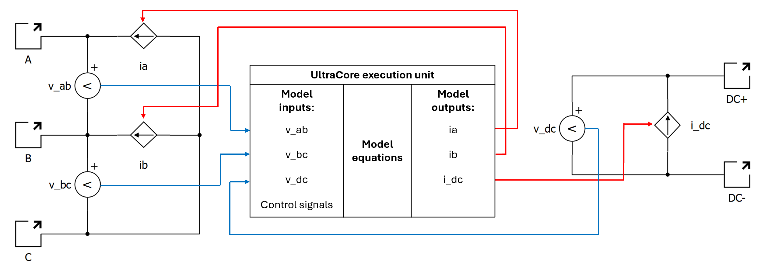
Besides ia, ib and i_dc which directly affect the surrounding circuit, there are additional component outputs:
- i_prim - represents the inductor's current
- i_prim.cmp_out - represents the comparator output of the i_prim signal against zero, using a greater or equal operator, updated at the solver simulation step
Digital Alias
If a converter is controlled by digital inputs, an alias for every digital input used by the converter will be created. Digital input aliases will be available under the Digital inputs list alongside existing Digital input signals. The alias will be shown as Converter_name.Switch_name, where Converter_name is name of the converter component and Switch_name is name of the controllable switch in the converter.
Ports
- A (electrical)
- AC-side phase A port.
- B (electrical)
- AC-side phase B port.
- C (electrical)
- AC-side phase C port.
- DC+ (electrical)
- DC-side positive port.
- DC- (electrical)
- DC-side negative port.
Control (Tab)
- S_A1
- Digital input that is used to control the S_A1 switch (AC phase A).
- S_A1_logic
- Logic that will be applied to the control signal for S_A1.
- Active high or active low.
- S_A2
- Digital input that is used to control the S_A2 switch (AC phase A).
- S_A2_logic
- Logic that will be applied to the control signal for S_A2.
- Active high or active low.
- S_A3
- Digital input that is used to control the S_A3 switch (AC phase A).
- S_A3_logic
- Logic that will be applied to the control signal for S_A3.
- Active high or active low.
- S_A4
- Digital input that is used to control the S_A4 switch (AC phase A).
- S_A4_logic
- Logic that will be applied to the control signal for S_A4.
- Active high or active low.
- S_B1
- Digital input that is used to control the S_B1 switch (AC phase B).
- S_B1_logic
- Logic that will be applied to the control signal for S_B1.
- Active high or active low.
- S_B2
- Digital input that is used to control the S_B2 switch (AC phase B).
- S_B2_logic
- Logic that will be applied to the control signal for S_B2.
- Active high or active low.
- S_B3
- Digital input that is used to control the S_B3 switch (AC phase B).
- S_B3_logic
- Logic that will be applied to the control signal for S_B3.
- Active high or active low.
- S_B4
- Digital input that is used to control the S_B4 switch (AC phase B).
- S_B4_logic
- Logic that will be applied to the control signal for S_B4.
- Active high or active low.
- S_C1
- Digital input that is used to control the S_C1 switch (AC phase C).
- S_C1_logic
- Logic that will be applied to the control signal for S_C1.
- Active high or active low.
- S_C2
- Digital input that is used to control the S_C2 switch (AC phase C).
- S_C2_logic
- Logic that will be applied to the control signal for S_C2.
- Active high or active low.
- S_C3
- Digital input that is used to control the S_C3 switch (AC phase C).
- S_C3_logic
- Logic that will be applied to the control signal for S_C3.
- Active high or active low.
- S_C4
- Digital input that is used to control the S_C4 switch (AC phase C).
- S_C4_logic
- Logic that will be applied to the control signal for S_C4.
- Active high or active low.
- S_H1
- Digital input that is used to control the S_H1 switch (DC-side H-bridge).
- S_H1_logic
- Logic that will be applied to the control signal for S_H1.
- Active high or active low.
- S_H2
- Digital input that is used to control the S_H2 switch (DC-side H-bridge).
- S_H2_logic
- Logic that will be applied to the control signal for S_H2.
- Active high or active low.
- S_H3
- Digital input that is used to control the S_H3 switch (DC-side H-bridge).
- S_H3_logic
- Logic that will be applied to the control signal for S_H3.
- Active high or active low.
- S_H4
- Digital input that is used to control the S_H4 switch (DC-side H-bridge).
- S_H4_logic
- Logic that will be applied to the control signal for S_H4.
- Active high or active low.
- Gate control enabling - AC-side
- If enabled, gives the possibility to control whether changes in the gate control signal are applied or not for the AC-side (matrix) bridge.
- Sen - AC
- Available if Gate control enabling - AC-side is enabled.
- Digital input that enables/disables switching for the AC-side bridge.
- Sen_logic - AC
- Available if Gate control enabling - AC-side is enabled.
- Logic that will be applied to the Sen - AC signal.
- Gate control enabling - DC-side
- If enabled, gives the possibility to control whether changes in the gate control signal are applied or not for the DC-side (H-bridge).
- Sen - DC
- Available if Gate control enabling - DC-side is enabled.
- Digital input that enables/disables switching for the DC-side bridge.
- Sen_logic - DC
- Available if Gate control enabling - DC-side is enabled.
- Logic that will be applied to the Sen - DC signal.
Electrical (Tab)
- Add Series Capacitor
- When enabled, adds a series DC-blocking capacitor to the circuit and exposes the C property.
- L
- Series inductance lumped to the AC side of the transformer.
- R
- Series resistance lumped to the AC side of the transformer. Rds(on) of the switches can be included in this resistance.
- C
- Series capacitance. Available only when Add Series Capacitor is enabled.
- Transformer turns ratio (DC/AC)
- Defines the internal transformer ratio between the DC and AC sides.
Extras (Tab)
- Short-circuit resistance - A
- Resistance for the AC side used to calculate the short-circuit current if the AC side is shorted.
- Short-circuit resistance - B
- Resistance for the DC side used to calculate the short-circuit current if the DC side is shorted.
- Public - Components marked as public expose their signals on all levels.
- Protected - Components marked as protected will hide their signals to components outside of their first locked parent component.
- Inherit - Components marked as inherit will take the nearest parent 'signal_access' property value that is set to a value other than inherit.