PHIL Interfaces
This section describes the general properties of Power Hardware-In-the-Loop (PHIL) interface components.
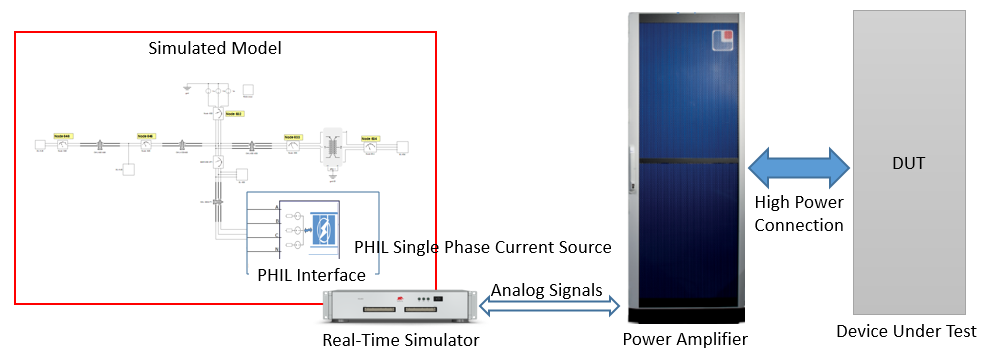
PHIL interface components are used to link the real time simulation with a real power amplifier to form a PHIL system, by means of analog input/output signals. PHIL interface components are composed of analog input controlled voltage/current sources and voltage/current measurements. In Figure 1 a typical PHIL setup is presented. It consists of a real-time simulator, a power amplifier, and a high power device under test. Depending on the purpose and function of the device under test, the power amplifier emulates either a grid or a load. The model simulated in the real-time simulator defines what exactly the power amplifier emulates. The real-time simulator is connected with the power amplifier through analog input and output signals. Through analog outputs, the real-time simulator sends the reference currents/voltages to the amplifier. These references are the results of the real-time simulation. The feedback signals from the power amplifier are used in the simulation through the analog inputs of the real-time simulator. The feedback signals are voltages or currents sensed by the power amplifier on its connection to the DUT. PHIL Interface components are used to easily select and parametrise which signals have to be sent or received from the power amplifier.
There are four PHIL interface components available in the library:
- PHIL Single Phase Current Source Interface
 TyphoonSim support - no
- PHIL Single Phase Voltage Source Interface
- TyphoonSim support - no
- PHIL Three Phase Current Source Interface
- TyphoonSim support - no
- PHIL Three Phase Voltage Source Interface
- TyphoonSim support - no
For all four interface component types the analog input pins, scaling factors and offsets can be defined. On top of that, a dedicated first order input filter can be enabled which is usually required to reduce the noise level on analog input signals. PHIL interface components are represented in the simulation as ideal voltage or current sources, therefore parallel or series resistances are included to avoid topological conflicts. The value for these resistances can be set in the Other tab. Besides electrical components, PHIL interface components also contain power measurement units implemented as a signal processing circuit, therefore the execution rate must be defined as well. The execution rate parameter is also in the Other tab.
Interface components support the Static and Dynamic settings options for analog input scaling factor and offset parametrization. Static settings means that the values are set in properties window of the PHIL interfaces component. If these are changed, the model needs to be recompiled. By enabling dynamic settings, the scaling factor and the offset will be tunable from Typhoon's SCADA during simulation runtime. The Dynamic option is not supported by all HIL device configurations. To use this option, the HIL configuration must support Time Varying Elements.