Test and Calibration Tool
Description of the Test and Calibration tool in Typhoon HIL Control Center
The Test and Calibration Tool performs an automated calibration of the analog IO section of HIL4- and HIL6-series devices. In addition, it checks for problems in the entire device interface; analog and digital IO sections, including externally available power supply levels, are validated. Both test and calibration procedures are fully automated. A valid license is required in order to run the tool.
Calibration Procedure
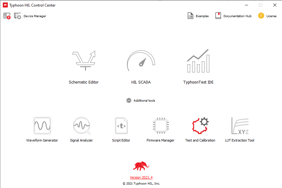
Start Typhoon HIL Control Center and click on Test and Calibration in the bottom right of the Additional tools dropdown, as shown in Figure 1.
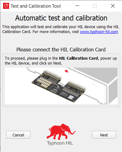
The Calibration Tool start screen will show up (Figure 2). To proceed, plug in your HIL Calibration Card, turn on the device, and then click Next.
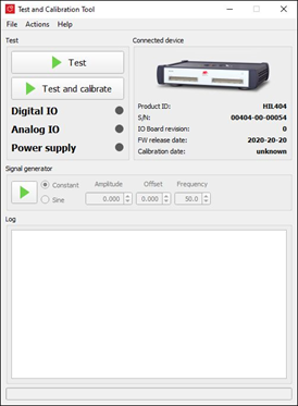
The main screen (Figure 3) will appear. To calibrate, click on the Test and Calibrate button.
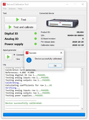
The outcome of a successful procedure is shown in Figure 4
Viewing the stored calibration data
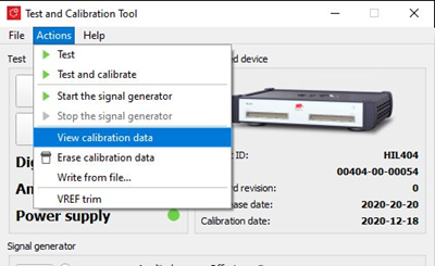
To view the stored calibration dataset, click on Actions -> View calibration data, as shown on Figure 5.
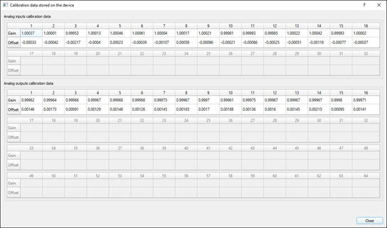
A window with values for gain and offset coefficients will appear (Figure 6).
Calibration card data (Vref Trim)
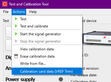
To view the stored calibration dataset, click on Actions -> Calibration card data (Vref Trim) as shown in Figure 7.
Calibration card data (Vref Trim) options
- VREF1 (positive)
- Measured voltage of the Calibration Card's negative voltage reference, positive value.
- VREF2 (negative)
- Measured voltage of the Calibration Card's negative voltage reference, negative value.
- Calib Card serial
- Serial number of the Calibration Card.
- Model Number
- Model number of the equipment used to measure the Calibration Card's onboard references.
- Equipment ID
- ID of the equipment used for measurement of Calibration Card onboard references.
- Date Used
- Date of measurement for the Calibration Card's onboard references.
- Cal Due Date
- Next calibration date for the measurement equipment.
Depending on the number of cards detected, the dialog will dynamically display only the detected cards (either the Top or Bottom card)
Erasing the calibration data
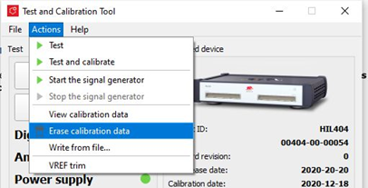
To erase the stored calibration constants (to set them to a neutral state), click on Actions -> Erase calibration, as shown in Figure 8.
Verifying the stored data
To manually verify that the device is correctly calibrated, a signal generator functionality is provided. The signal generator is embedded in the main app screen, as shown in Figure 9.
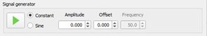
The generator will set the specified signal on all outputs. You can then take a high accuracy multimeter and measure the outputs, to ensure that it is within spec.
Manual calibration mode
A manual write-from-file function is provided, in case you want to calculate and write the coefficients manually. The coefficients are read from the provided .txt file, and stored onto the device flash.
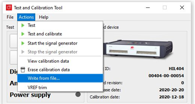
To access this function, click on Actions -> Write from file..., as shown in Figure 10.
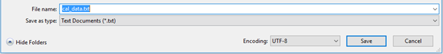
The encoding format of the expected file is UTF-8. A screenshot from Microsoft Notepad is shown in Figure 11.
The structure of the expected file is given in Table 1.
| AI_GAIN[1] | AI_GAIN[2] | AI_GAIN[3] | ... | AI_GAIN[N] |
| AI_OFFSET[1] | AI_OFFSET[2] | AI_OFFSET[3] | ... | AI_OFFSET[N] |
| AO_GAIN[1] | AO_GAIN[2] | AO_GAIN[3] | ... | AO_GAIN[N] |
| AO_OFFSET[1] | AO_OFFSET[2] | AO_OFFSET[3] | ... | AO_OFFSET[N] |
The file should contain four rows of constants. The values on each line should be TAB or SPACE delimited.
If an invalid format, insufficient values, or invalid coefficients are used, the procedure will be aborted.