Detailed description
Detailed description of the HIL4 Calibration Card and HIL6 Calibration Card
Method of operation
Both HIL4 and HIL6 Calibration Cards operate in the same manner, and offer the following high-level routines:
- Test routine - checks for errors on the digital, analog, and PSU sections
- Test and Calibration routine - calibrates all analog channels
The Test routine consists of the following steps:
- Digital Outputs (DOs) are tested via Digital Inputs (DIs)
- Analog Inputs (AIs) are tested via the Voltage Reference (VR) section on the Calibration Card
- Analog Outputs (AOs) are tested via the AIs
- Power Supplies are measured via the AIs
The Test and Calibration routine consists of the following steps:
- The whole I/O is checked for faults, with loose tolerances, via the Test routine
- AIs are calibrated via the VR section
- AOs are calibrated via the AIs
- The whole I/O is checked again, with tight tolerances, via the Test routine
Screenshots and a more detailed guide to the companion app used for executing these routines, are available on Test and Calibration Tool.
Layout
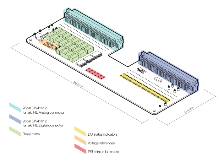
The board features the following key sections, as shown in Figure 1.
- HIL Analog connector
- HIL Digital connector
- DO status indicators
- PSU status indicators
- Relay matrix
- Voltage references
HIL Analog I/O
This connector will take all signals from the Analog I/O connector, found on any supported HIL device, and route them to the Relay matrix.
HIL Digital I/O
This 96-pin DIN41612 female connector interfaces with the Digital I/O connector, on any supported HIL device. Signals from this connector are arranged in a loop-back fashion, as each Digital Input channel is physically short-circuited to its corresponding Digital Output channel.
Relay matrix
This section routes signals, in a manner which supports the Test and Calibrate function.
PSU and DO status indicators
To verify that the HIL under test is performing as expected, both PSU and DO sections feature one white LED per channel.
The PSU status LEDs must be turned ON, when the User PSU section on the HIL is operational.
The DO status LEDs are turned ON whenever a DO is switched to a logic high level.
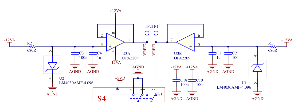
Voltage references
The basis of the whole calibration algorithm are two LM4030AMF-4.096 shunt voltage references. These two references form two reference levels, +4.096 V and -4.096 V, as shown in Figure 2.
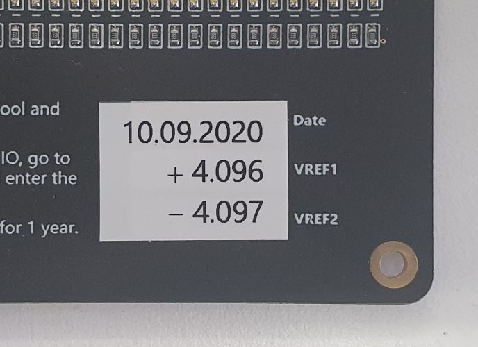
The voltage reference ICs values are measured in the Typhoon HIL factory, and the values printed out on the Calibration Card, as shown in Figure 3. The measurements are valid for 1 year.