Machines
This section describes the concepts used in the modeling and implementation of electrical machine components in Typhoon HIL Schematic Editor.
Machine components implementation
All electrical machine components consist of two parts:
- the electrical circuit interface
- the MachineCore
The signals measured in the circuit interface are used as inputs to the MachineCore. The MachineCore then calculates the model outputs and feeds them to the controlled sources in the circuit interface.
Circuit interface
The machine components in the Typhoon HIL Schematic Editor Library use two types of circuit interfaces, the current source interface, and the voltage behind reactance interface (VBR). When using the current source interface, the machine model equations are formulated in such a way that the voltages are inputs, while the currents are outputs. Conversely, when using the voltage behind reactance interface, the machine model equations are formulated in such a way that the currents are inputs, while the voltages are outputs. Stator, rotor, and field winding variables can be found as machine_name.winding.variable_name in HIL SCADA and TyphoonSim Scope.
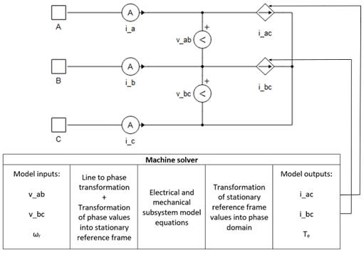
Current sources implementation variables:
- v_ab
- Measured line voltage between terminals A and B [V]
- v_bc
- Measured line voltage between terminals B and C [V]
- ωr
- Rotor mechanical speed [rad/s]
- i_ac
- Calculated phase A current [A]
- i_bc
- Calculated phase B current [A]
- Te
- Machine developed electromagnetic torque [Nm]
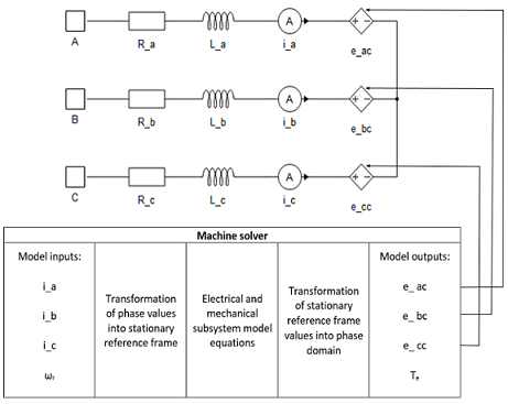
Voltage behind reactance implementation variables:
- i_a
- Measured phase A current [A]
- i_b
- Measured phase B current [A]
- i_c
- Measured phase C current [A]
- ωr
- Rotor mechanical speed [rad/s]
- e_ac
- Calculated phase A induced back emf [V]
- e_bc
- Calculated phase B induced back emf [V]
- e_cc
- Calculated phase C induced back emf [V]
- Te
- Machine developed electromagnetic torque [Nm]
Machine models in real-time/VHIL
The real-time/VHIL MachineCore is a dedicated module that simulates the electrical and mechanical parts of the machine model, as well as the encoder and resolver feedback signals. Electrical subsystem model equations are used for calculating machine electrical variables. The motion equation and the machine electrical torque expression are used to calculate machine mechanical variables. Nonlinear effects such as flux saturation and spatial harmonics are modeled as lookup tables. The number of points available for the lookup tables used in a single machine component is 215. If the total number of points provided in the lookup tables exceeds this number, the tables will be rescaled to work with fewer points. The resulting tables may have a lower resolution than the original ones. The lookup tables use linear interpolation and linear extrapolation.
Machine models in TyphoonSim
Machine models in TyphoonSim are implemented using controlled current sources or voltage behind reactance (VBR) interfaces. In both implementations, phase voltages and currents are sampled at each time step and are used to solve the machine’s state space model.
Machine models are currently using an explicit first order Euler integration method which is separate from the main solver and is suitable for obtaining stable results at small time steps. More sophisticated integration methods for machine models are planned in future updates.
For machines with current source interface, phase voltages are sampled as inputs to the model and machine stator and (if a rotor circuit exists) rotor fluxes or currents are chosen as state variables. Machine currents are then calculated according to the machine mathematical model in either αβ0 or dq0 coordinates and are converted to the phase domain and applied to the current sources.
In the voltage behind reactance (VBR) implementation, in case the machine has a rotor circuit, rotor fluxes are chosen as state variables with stator currents as inputs to the state-space model. This state-space model is then used to represents the machine rotor as a controlled voltage source connected in series to an equivalent inductor and further to the stator equivalent circuit in either αβ0 or qd0 coordinates. The VBR configuration is then interfaced in phase coordinates to the rest of the circuit. The phase voltage is used as an input to provide necessary calculations to obtain a constant parameter (R and L) interface only when machine has saliency or when nonlinear properties, such as saturation, are modeled.
Reference frames
Reference frame transformations are commonly used to eliminate time-varying inductances in the machine model. Unless otherwise noted, all of the machine models in the Typhoon HIL Schematic Editor Library are implemented using one of the following reference frames:
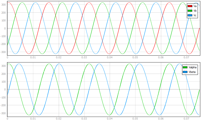
Stationary αβ reference frame
Clarke's transformation transforms stator and rotor electrical variables from the original three phase domain into a stationary two phase αβ domain.
Electrical variables are transformed to αβ components using the transformation matrix:
In order to keep the same amplitude of the electrical variables as in the original phase domain, a multiplier of 2/3 is introduced in the abc/αβ transformation matrix. θab determines the position of the used stationary reference frame with regard to the stator phase winding a.
Three phase quantities are transformed to αβ components using the equation:
where X represents a vector of voltages, currents, or fluxes.
Stationary αβ components of electrical variables are transformed to phase values using the inverse Clarke's transformation matrix in the following form:
αβ components of three phase quantities are transformed to phase components using the equation:
where X represents a vector of voltages, currents, or fluxes.
The general form of the αβ transformation matrix for the n-phase machine is given by:
where n is the number of phases.
The first two rows of the matrix define variables that will lead to fundamental flux and torque production. The last two rows define the two zero sequence components, and the last row of the transformation matrix is omitted for all odd phase numbers n. In between, there are (n - 4)/2 pairs of rows which define (n - 4)/2 pairs of variables for even phase numbers, and (n - 3)/2 pairs of rows and variables for odd phase numbers. These components correspond to certain voltage, flux, and current harmonics and do not contribute to torque production.
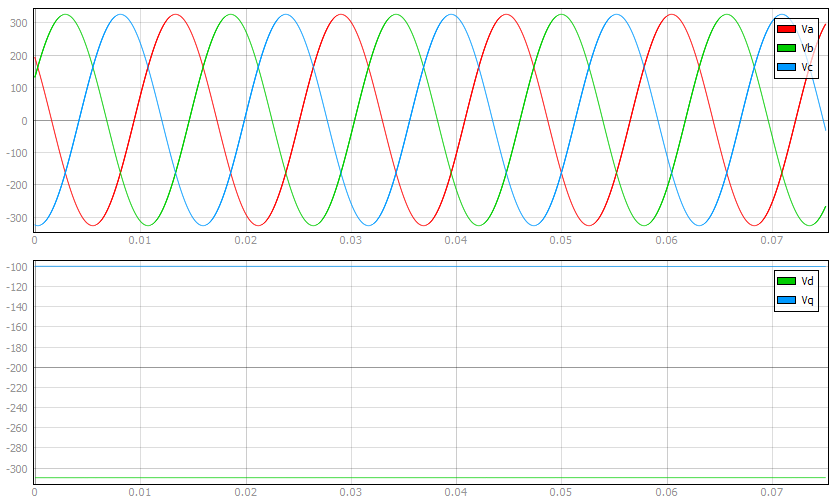
Rotating dq reference frame
Park's transformation transforms stator and rotor electrical variables from the original three phase domain into a rotating two phase dq domain.
Electrical variables are transformed to dq components using the transformation matrix:
The position of the rotating frame is given by ωt, where ω represents the dq frame rotation speed. θab determines the position of the used rotating reference frame with regard to the stator phase winding a.
Three phase quantities are transformed to dq components using the equation:
where X represents a vector of voltages, currents, or fluxes.
Rotating dq components of electrical variables are transformed to phase values using the inverse Park's transformation matrix in the following form:
dq components of three phase quantities are transformed to phase components using the equation:
where X represents a vector of voltages, currents, or fluxes.
Machines Library Components
The current version of Typhoon HIL Schematic Editor offers a selection of the following types of machine components:
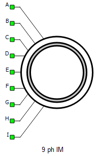
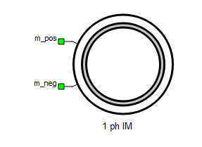
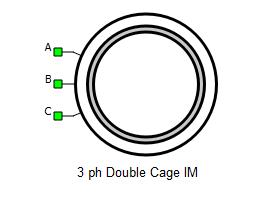
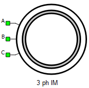
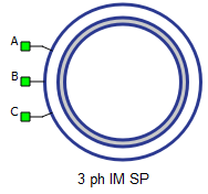
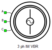
Induction Machines components are intended for real-time modeling of specific types of induction machines, as shown in Table 1.
| Component Name | Component Image | Schematic Editor Library |
|---|---|---|
 |
Library Explorer: Machines/Induction Machines |
|
 |
Library Explorer: Machines/Induction Machines |
|
 |
Library Explorer: Machines/Induction Machines |
|
 |
Library Explorer: Machines/Induction Machines |
|
|
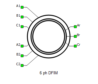
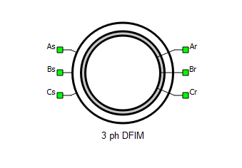
Three Phase Doubly Fed Induction Machine* *This component supports Saturable Leakage Inductance |
 |
Library Explorer: Machines/Induction Machines |
 |
Library Explorer: Machines/Induction Machines |
|
 |
Library Explorer: Machines/Induction Machines |
|
 |
Library Explorer: Machines/Induction Machines |
|
 |
Library Explorer: Machines/Induction Machines |
|
 |
Library Explorer: Machines/Induction Machines |
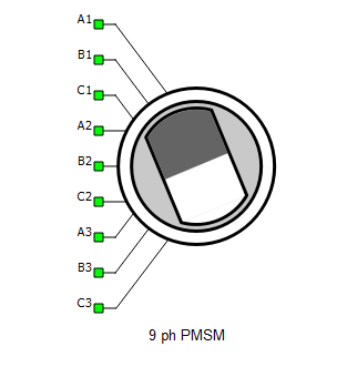
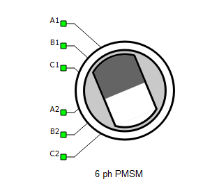
Synchronous Machines components are intended for real-time modeling of specific types of synchronous machines, as shown in Table 2.
| Component Name | Component Image | Schematic Editor Library |
|---|---|---|
|
Nine Phase Permanent Magnet Synchronous Machine (Triple Stator) |
 |
Library Explorer: Machines/Synchronous Machines |
|
Six Phase Permanent Magnet Synchronous Machine (Double Stator) |
 |
Library Explorer: Machines/Synchronous Machines |
 |
Library Explorer: Machines/Synchronous Machines |
|
|
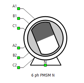
Six Phase Permanent Magnet Synchronous Machine with Neutral Connection |
 |
Library Explorer: Machines/Synchronous Machines |
|
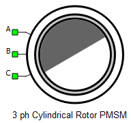
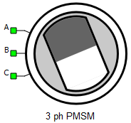
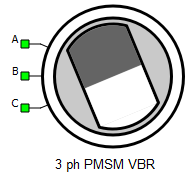
Three Phase Cylindrical Rotor Permanent Magnet Synchronous Machine |
 |
Library Explorer: Machines/Synchronous Machines |
|
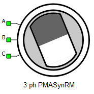
Three Phase Permanent Magnet Assisted Synchronous Reluctance Machine |
 |
Library Explorer: Machines/Synchronous Machines |
 |
Library Explorer: Machines/Synchronous Machines |
|
|
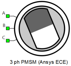
Three Phase Permanent Magnet Synchronous Machine (Ansys ECE) |
 |
Library Explorer: Machines/Synchronous Machines |
 |
Library Explorer: Machines/Synchronous Machines |
|
|
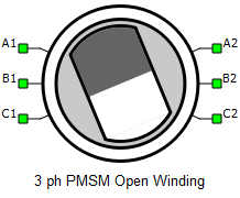
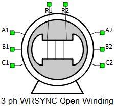
Three Phase Permanent Magnet Synchronous Machine (Open Winding) |
 |
Library Explorer: Machines/Synchronous Machines |
 |
Library Explorer: Machines/Synchronous Machines |
|
|
Three Phase Permanent Magnet Synchronous Machine with Neutral Connection |
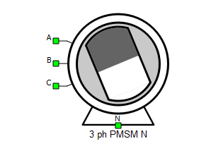 |
Library Explorer: Machines/Synchronous Machines |
 |
Library Explorer: Machines/Synchronous Machines |
|
 |
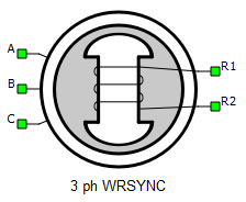
Library Explorer: Machines/Synchronous Machines |
|
 |
Library Explorer: Machines/Synchronous Machines |
|
|
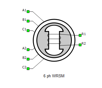
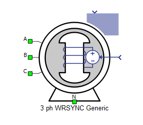
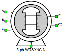
Three Phase Wound Rotor Synchronous Machine with Neutral Connection |
 |
Library Explorer: Machines/Synchronous Machines |
|
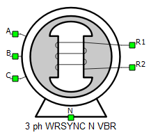
Three Phase Wound Rotor Synchronous Machine with Neutral Connection (VBR) |
 |
Library Explorer: Machines/Synchronous Machines |
Additionally, the following machine types also have dedicated components:
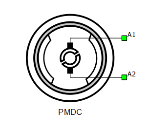
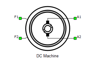
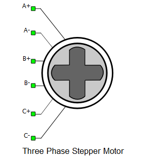
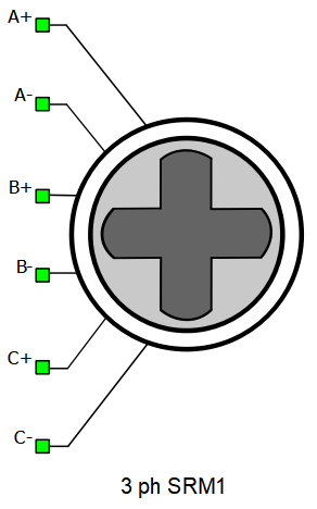
| Component Name | Component Image | Schematic Editor Library |
|---|---|---|
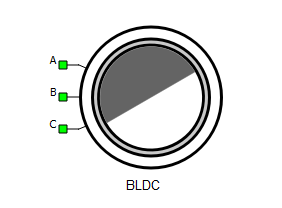 |
Library Explorer: Machines |
|
 |
Library Explorer: Machines |
|
 |
Library Explorer: Machines |
|
 |
Library Explorer: Machines |
|
 |
Library Explorer: Machines |
References
Machine components were implemented based on the principles described in the following literature:
- Analysis of electric machinery, Paul Krause, New York: McGraw-Hill, c1986
- Paul C. Krause., Oleg Wasynczuk, and Scott D. Sudhoff, Analysis of Electric Machinery, IEEE Press, 2002.
- Liwei Wang, Modeling of AC machines using a voltage-behind-reactance formulation of electromagnetic transients in power systems, The University of British Columbia, Vancouver, 2010.
- Robert Vartanian, Permanent Magnet Assisted Synchronous Reluctance Machine (PMa-SynRM) Design and Performance Analysis for Fan and Pump Applications, Doctoral dissertation at Texas A & M University, 2014.
- Xiao Chen, Jiabin Wang, Bhaskar Sen, Panagiotis Lazari, Tianfu Sun, A High-Fidelity and Computationally Efficient Model for Interior Permanent-Magnet Machines Considering the Magnetic Saturation, Spatial Harmonics, and Iron Loss Effect, IEEE, 2015.
- I. M. Canay, Causes of Discrepancies on Calculation of Rotor Quantities and Exact Equivalent Diagrams of the Synchronous Machine, IEEE, 1969.
- Alberto Berzoy, Ahmed A. S. Mohamed, Osama Mohammed, Complex-Vector Model of Interturn Failure in Induction Machines for Fault Detection and Identification, IEEE, 2016.
- Liwei Wang, Juri Jatskevich, Steven D. Pekarek, Modeling of Induction Machines Using a Voltage-Behind-Reactance Formulation, IEEE, 2008.
- Emil Levi, Radu Bojoi, F. Profumo, Hamid Toliyat, Multiphase induction motor drives - A technology status review, IET Electric Power Applications, 2007.