Hall Effect Sensor
Description of the Hall Effect Sensor component in Schematic Editor, which is used to detect the rotor position of the machines.
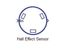
Component Icon
Description
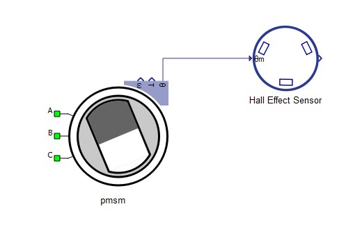
This component connects to the machine mechanical angle output as shown in Figure 2. The output of the component is a single vectorized signal processing output which contains digital signals Hall A, Hall B and Hall C.
It is executed at the signal processing execution rate, therefore the execution rate should be taken into account.
The hall effect sensor operation principle is based on three digital outputs whose values determine six possible position segments. Table 1 shows the position segments based on the state of the digital outputs.
is the machine electrical angle given by:
, where is the number of pole pairs.
| Position segment | Hall A | Hall B | Hall C |
|---|---|---|---|
| 1 | 0 | 0 | |
| 1 | 1 | 0 | |
| 0 | 1 | 0 | |
| 0 | 1 | 1 | |
| 0 | 0 | 1 | |
| 1 | 0 | 1 |
Ports
- θm
- Mechanical angle input [rad]
- out
- Vectorized signal processing output which contains digital Hall A, Hall B, and Hall C signals
Properties
- Number of pole pairs
- Number of the rotor pole pairs of connected machine
- Execution rate
- Signal processing output execution rate [s]