Three Phase Squirrel Cage Induction Machine (SP)
Description of the Three Phase Squirrel Cage Induction Machine (SP) component in Schematic Editor.
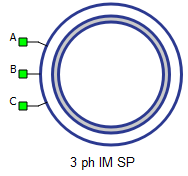
A, B, and C are the stator winding terminals. The stator winding uses the current source interface.
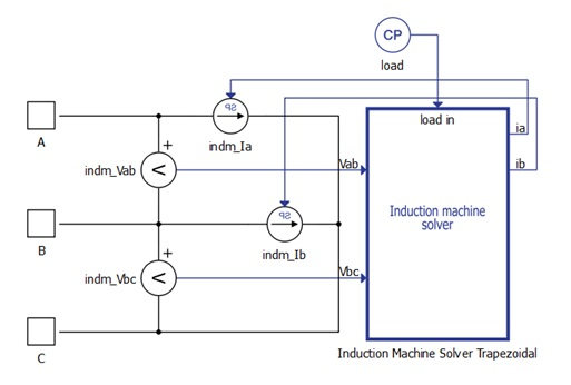
This machine is an alternative implementation of the Three Phase Squirrel Cage Induction Machine which relies on Signal Processing, shown by the "SP" in the component name. It is a hybrid component, consisting of both an electrical part and a signal processing part (Figure 2). The electrical part consists of two controlled current sources and snubber resistances, while the complete machine model including its electrical and mechanical equations, is implemented as C functions in the signal processing part of the circuit.
The advantage of this machine is that it doesn't use the hardware MachineCore of the processor, so the number of machines per HIL is not limited. The drawback is that this machine model is executed with solver execution rates rather than the chosen simulation step of the electrical circuit. This means the SP induction machine execution rate depends on the number of component instances in the model and it is usually in range of 10 – 100 μs.
Electrical sub-system model
The electrical part of the machine is represented by the following system of equations, modeled in the stationary αβ reference frame. All rotor variables and parameters are referred to the stator.
| Symbol | Description |
|---|---|
| ψαs | Alpha axis component of the stator flux [Wb] |
| ψβs | Beta axis component of the stator flux [Wb] |
| ψαr | Alpha axis component of the rotor flux, referred to the stator [Wb] |
| ψβr | Beta axis component of the rotor flux, referred to the stator [Wb] |
| iαs | Alpha axis component of the stator current [A] |
| iβs | Beta axis component of the stator current [A] |
| iαr | Alpha axis component of the rotor current, referred to the stator [A] |
| iβr | Beta axis component of the rotor current, referred to the stator [A] |
| vαs | Alpha axis component of the stator voltage [V] |
| vβs | Beta axis component of the stator voltage [V] |
| vαr | Alpha axis component of the rotor voltage, referred to the stator [V] |
| vβr | Beta axis component of the rotor voltage, referred to the stator [V] |
| Rs | Stator phase resistance [Ω] |
| Rr | Rotor phase resistance, referred to the stator [Ω] |
| Lm | Magnetizing (mutual, main) inductance [H] |
| Ls | Stator phase inductance [H] ( ) |
| Lr | Rotor phase inductance, referred to the stator [H] ( ) |
| ωr | Rotor electrical speed [rad/s] ( ) |
| p | Machine number of pole pairs |
| Te | Machine developed electromagnetic torque [Nm] |
Mechanical sub-system model
Motion equation:
| Symbol | Description |
|---|---|
| ωm | Rotor mechanical speed [rad/s] |
| Jm | Combined rotor and load moment of inertia [kgm2] |
| Te | Machine developed electromagnetic torque [Nm] |
| Tl | Shaft mechanical load torque [Nm] |
| b | Machine viscous friction coefficient [Nms] |
| θm | Rotor mechanical angle [rad] |
Ports
- A (electrical)
- Stator winding phase A port.
- B (electrical)
- Stator winding phase B port.
- C (electrical)
- Stator winding phase C port.
- in
- Available if Model Load source is selected.
Electrical (Tab)
- f
- Machine rated frequency [Hz]
- Rs
- Stator phase resistance [Ω]
- Rr
- Rotor phase resistance, referred to the stator [Ω]
- Lls
- Stator leakage inductance [H]
- Llr
- Rotor leakage inductance, referred to the stator [H]
- Lm
- Magnetizing (mutual, main) inductance [H]
Mechanical (Tab)
- pms
- Machine number of pole pairs
- Jm
- Combined rotor and load moment of inertia [kgm2]
- Friction coefficient
- Machine viscous friction coefficient [Nms]
Load (Tab)
- Load source
- Load source can be set from SCADA/external or from model (in model case, one signal processing input will appear).
- External/Model load type
- Load type: torque or speed
Measurements (Tab)
This block tab enables a single, vectorized signal output from the machine. The output vector contains selected machine mechanical and/or electrical variables in the same order as listed in this tab.
- Stator phase A current
- Stator phase A current [A]
- Stator phase B current
- Stator phase B current [A]
- Stator phase C current
- Stator phase C current [A]
- Electrical torque
- Machine electrical torque [Nm]
- Mechanical speed
- Machine mechanical angular speed [rad/s]
- Mechanical angle
- Machine mechanical angle [rad]
Execution rate (Tab)
- Execution rate
- Signal processing execution rate [s]
Snubber (Tab)
- Snubber Resistance
- Stator snubber resistance value [Ω]
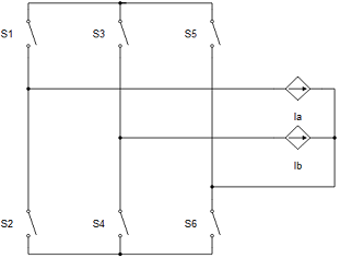
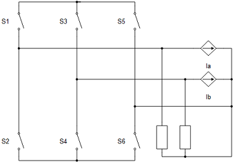
All machines with current source based circuit interfaces have the Snubber tab in the properties window where the value of snubber resistance can be set. Snubbers are necessary in the cases when an inverter or a contactor is directly connected to the machine terminals. This value can be set to infinite (inf), but it is not recommended when a machine is directly connected to the inverter since there will be a current source directly connected to an open switch. In this case, one of each switch pairs S1 and S2, S3 and S4, and S5 and S6 will be forced closed by the circuit solver in order to avoid the topological conflicts. On the other hand, with finite snubber values, there's always a path for the currents Ia and Ib, so all inverter switches can be open in this case. Circuit representations of this circuit without and with snubber resistors are shown in Figure 3 and Figure 4 respectively. Snubbers are connected across the current sources.
Extras (Tab)
The Extras tab gives you the opportunity to set Signal Access Management for the component.
- Public - Components marked as public expose their signals on all levels.
- Protected - Components marked as protected will hide their signals to components outside of their first locked parent component.
- Inherit - Components marked as inherit will take the nearest parent 'signal_access' property value that is set to a value other than inherit.