MMC Leg - Switching Function
Description of the MMC Leg - Switching Function component in Schematic Editor
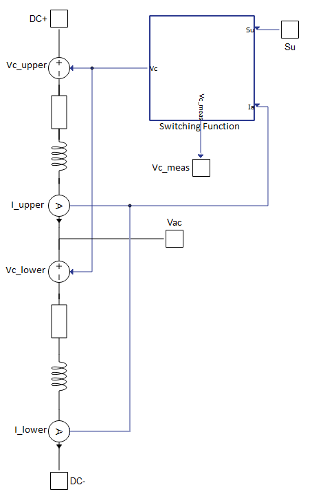
Schematic Block Diagram
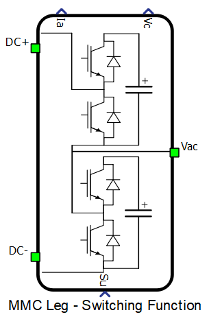
MMC Leg - Switching Function is composed of two arms - upper and lower. Each arm consists of a series connection of voltage source (Vc_upper and Vc_lower), resistor, inductor and current measurement (I_upper and I_lower) shown in schematic block diagram below. Voltage source is controlled by Switching Function block (it replaces all capacitors and switches in arm) and represents a sum of all voltages across capacitors that are currenlty inserted in the arm. Inputs in this block are current measurements of both arms and an array Su which represents switching states for each sub-module. For example, in case when the value of element in the array Su is equal to 1, current will flow through the capacitor and if the value of element is equal to 0, current will bypass the capacitor. Number of voltage levels is determined by the length of array Su.
Control for MMC Leg - NLC is a compatible component in our library for internal control the MMC Leg - Switching Function.
Ports
- DC+ (electrical)
- DC side + port.
- DC- (electrical)
- DC side - port.
- Vac (electrical)
- AC side port
- Su
- A digital input that determinates which sub-modules will be inserted in the circuit.
- Ia
- The measured currents in both arms are provided as an array through analog output.
- Vc
- The measured voltages across the capacitors in both arms are provided as an array through analog output.
General (Tab)
- Execution rate
- Execution rate of all signal processing components in a model.
- Resistance
- Arm resistance.
- Inductance
- Arm inductance.
- Capacitance
- Capacitance of each capacitor in a leg.
- Capacitor initial voltage
- Initial voltage across each capacitor in a leg.
Measurements (Tab)
- Enable upper and lower arm voltages
- Enables observation of instantaneous voltage measurements, separately in upper and lower arm.
Extras (Tab)
- Public - Components marked as public expose their signals on all levels.
- Protected - Components marked as protected will hide their signals to components outside of their first locked parent component.
- Inherit - Components marked as inherit will take the nearest parent 'signal_access' property value that is set to a value other than inherit.