
Three Phase Dual Active Bridge
Description of the Three Phase Dual Active Bridge converter in Schematic Editor.
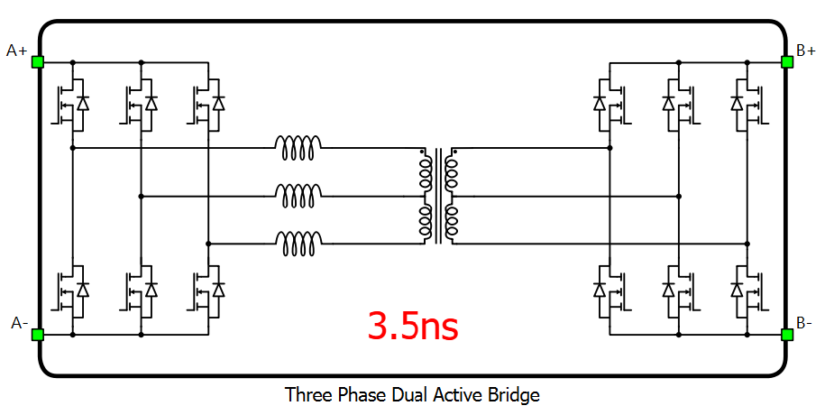
Schematic Block Diagram
The Three Phase Dual Active Bridge is the three-phase counterpart of the Dual Active Bridge. It consists of two three-phase two-level inverter bridges, the A-side bridge and the B-side bridge, each built from three legs. Leg 1 of the A-side bridge is formed by switches SA_1 and SA_2, leg 2 by SA_3 and SA_4, and leg 3 by SA_5 and SA_6; the B-side bridge follows the same naming with switches SB_1 to SB_6. A schematic block diagram of the Three Phase Dual Active Bridge with corresponding switch naming is given in Figure 2.
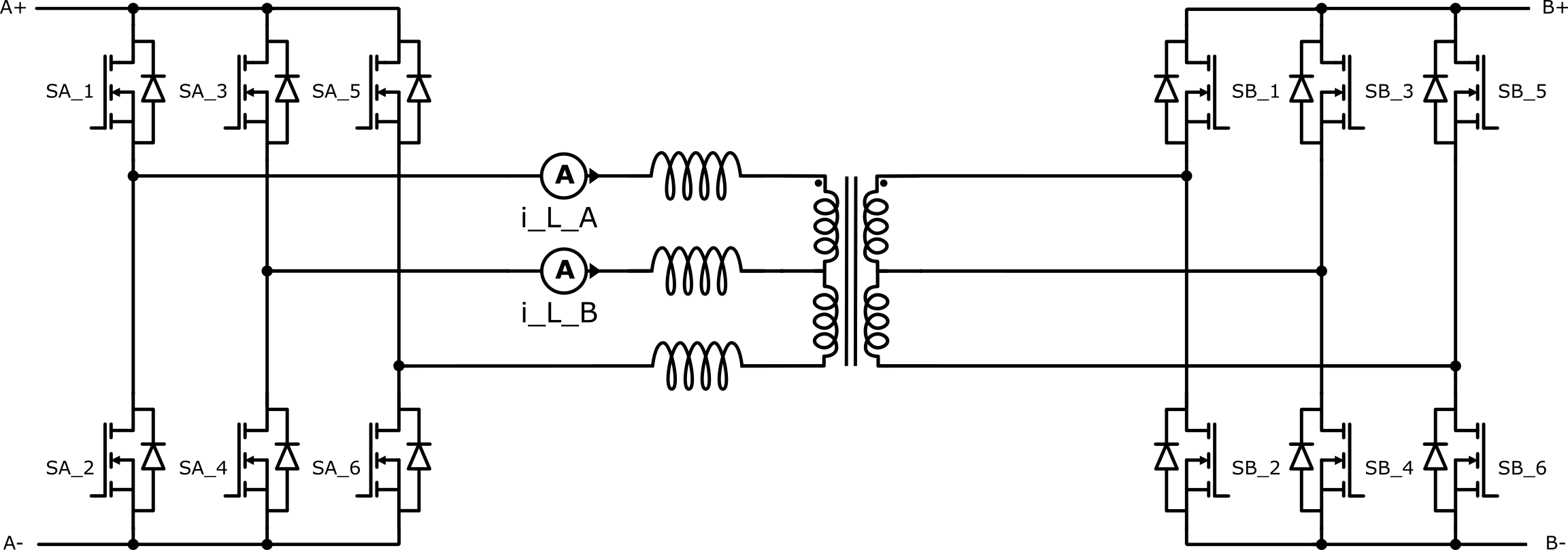
In real-time simulation, this converter block uses the dedicated UltraCore FPGA hardware resource in order to achieve a reduced simulation step for this topology. UltraCore weight of the Three Phase Dual Active Bridge is 3.
Control
Selecting Digital inputs as the Control parameter enables assigning gate drive inputs to any of the digital input pins (from 1 to 32(64)). For example, if SA_1 is assigned to 1, the digital input pin 1 will be routed to the SA_1 switch gate drive. In addition, the gate_logic parameter selects either active high (High-level input voltage VIH turns on the switch), or active low (Low-level input voltage VIL turns on the switch) gate drive logic, depending on the design of the external controller.
Selecting Internal modulator as the Control parameter enables use of a six-channel internal PWM modulator for driving the switches instead of digital input pins. In this configuration, five additional component inputs will be present. The En input is used to enable/disable the internal PWM modulator. In_A is the referent signal input shared by all three legs of the A-side bridge, and In_B is the referent signal input shared by all three legs of the B-side bridge. Offset_A and Offset_B are three-element vector inputs that define the carrier phase offsets of the individual legs of the A-side and B-side bridges, respectively. If Variable carrier frequency is selected as the Operation mode for the internal modulator, an additional port Freq will be present. This port is used as a frequency input for the internal PWM modulator.
Extras
In real-time simulation, Short-circuit resistance - A and Short-circuit resistance - B are used to define the resistance that will be taken into consideration if some of the legs goes to short-circuit mode. Short-circuits are modelled using short-circuit resistance, which means that if a leg is in short-circuit mode, current drawn from its corresponding DC side will be Vdc_A(B)/Short-circuit resistance - A(B), where Vdc_A(B) is the DC voltage of the corresponding DC side.
Model description in real-time simulation
In real-time simulation, the Three Phase Dual Active Bridge runs on a dedicated UltraCore hardware solver module, which is highly optimized to simulate the dynamics of fast-switching converter topologies with enhanced resolution. This means that the Three Phase Dual Active Bridge converter block does not utilize the same resources that are typically used for other converter blocks, and the SPC weight of the Three Phase Dual Active Bridge converter for real-time simulation is 0.
Electrical circuit interface in real-time simulation
As described in Electrical circuit interface, every component that uses the UltraCore hardware resource contains an interfacing electrical circuit towards the rest of the circuit. The Three Phase Dual Active Bridge component in the Typhoon HIL Schematic Editor Library uses the current source interface. The interface is formulated in such a way that the voltages are inputs to the dedicated UltraCore execution unit, while the currents are its outputs. Figure 3 shows the circuit interface of the Three Phase Dual Active Bridge component.
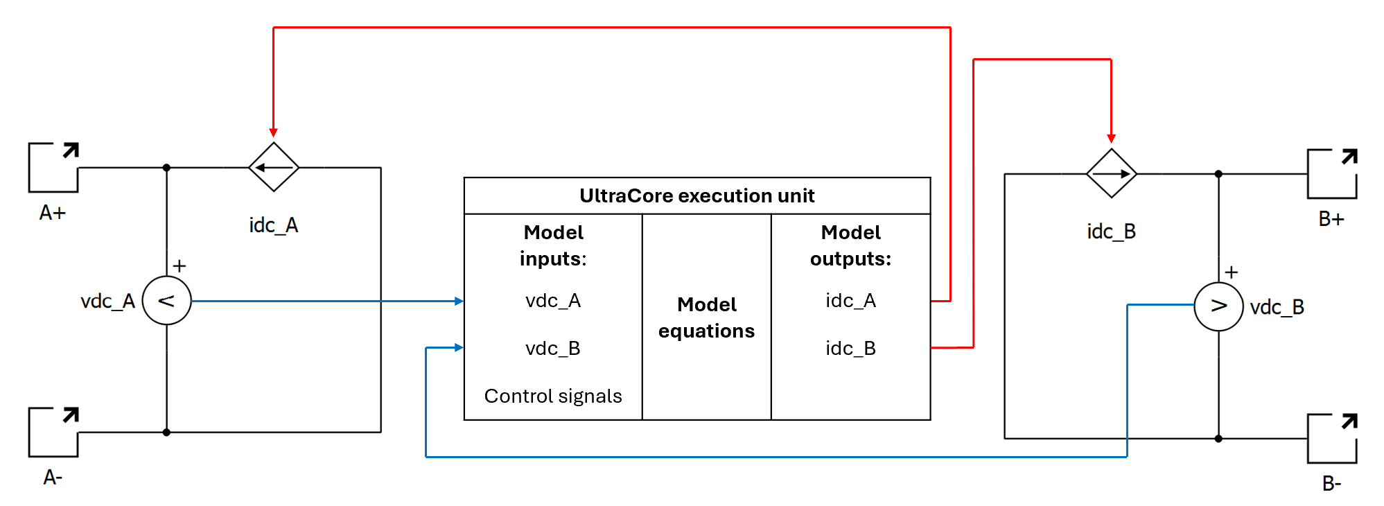
Besides IA and IB which directly affect the surrounding circuit, there are additional component outputs:
- i_L_A - represents the inductor current of the first phase
- i_L_B - represents the inductor current of the second phase
Since the phase currents sum to zero, the inductor current of the third phase is equal to -(i_L_A + i_L_B).
Digital Alias
If a converter is controlled by digital inputs, an alias for every digital input used by the converter will be created. Digital input aliases will be available under the Digital inputs list alongside existing Digital input signals. The alias will be shown as Converter_name.Switch_name, where Converter_name is name of the converter component and Switch_name is name of the controllable switch in the converter.
Ports
- A+ (electrical)
- DC side A+ port.
- A- (electrical)
- DC side A- port.
- B+ (electrical)
- DC side B+ port.
- B- (electrical)
- DC side B- port.
- En (in)
- Available if Internal modulator control is selected
- Used to enable/disable internal modulator
- In_A (in)
- Available if Internal modulator control is selected
- Used to specify modulation signal value for internal modulator in all three legs of the A-side bridge
- In_B (in)
- Available if Internal modulator control is selected
- Used to specify modulation signal value for internal modulator in all three legs of the B-side bridge
- Offset_A (in)
- Available if Internal modulator control is selected
- Three-element vector used to specify modulator's carrier phase offsets in the legs of the A-side bridge
- Offset_B (in)
- Available if Internal modulator control is selected
- Three-element vector used to specify modulator's carrier phase offsets in the legs of the B-side bridge
- Freq (in)
- Available if Internal modulator control is selected and Variable carrier frequency is selected as the modulator's operation mode
- Used to specify modulator's carrier frequency
Control (Tab)
- Control
- Specifies how switches are controlled. It is possible to choose between: Digital inputs and Internal modulator
- More details about each type of control can be found in the Control section
- If Digital inputs is selected as Control, the following
properties can be used:
- SA_1
- Digital input that is used to control SA_1 switch
- SA_1_logic
- Logic that will be applied to control signal for SA_1
- Active high or active low
- SA_2
- Digital input that is used to control SA_2 switch
- SA_2_logic
- Logic that will be applied to control signal for SA_2
- Active high or active low
- SA_3
- Digital input that is used to control SA_3 switch
- SA_3_logic
- Logic that will be applied to control signal for SA_3
- Active high or active low
- SA_4
- Digital input that is used to control SA_4 switch
- SA_4_logic
- Logic that will be applied to control signal for SA_4
- Active high or active low
- SA_5
- Digital input that is used to control SA_5 switch
- SA_5_logic
- Logic that will be applied to control signal for SA_5
- Active high or active low
- SA_6
- Digital input that is used to control SA_6 switch
- SA_6_logic
- Logic that will be applied to control signal for SA_6
- Active high or active low
- SB_1
- Digital input that is used to control SB_1 switch
- SB_1_logic
- Logic that will be applied to control signal for SB_1
- Active high or active low
- SB_2
- Digital input that is used to control SB_2 switch
- SB_2_logic
- Logic that will be applied to control signal for SB_2
- Active high or active low
- SB_3
- Digital input that is used to control SB_3 switch
- SB_3_logic
- Logic that will be applied to control signal for SB_3
- Active high or active low
- SB_4
- Digital input that is used to control SB_4 switch
- SB_4_logic
- Logic that will be applied to control signal for SB_4
- Active high or active low
- SB_5
- Digital input that is used to control SB_5 switch
- SB_5_logic
- Logic that will be applied to control signal for SB_5
- Active high or active low
- SB_6
- Digital input that is used to control SB_6 switch
- SB_6_logic
- Logic that will be applied to control signal for SB_6
- Active high or active low
- Gate control enabling - A
- If enabled, gives a possibility to control if changes in the gate control signal are applied or not for converter A
- Sen - A
- Available if Gate control enabling - A is enabled
- Digital input that enables/disables switching for converter A
- Sen_logic - A
- Available if Gate control enabling - A is enabled
- Logic that will be applied to Sen - A signal
- Gate control enabling - B
- If enabled, gives a possibility to control if changes in the gate control signal are applied or not for converter B
- Sen - B
- Available if Gate control enabling - B is enabled
- Digital input that enables/disables switching for converter B
- Sen_logic - B
- Available if Gate control enabling - B is enabled
- Logic that will be applied to Sen - B signal
- SA_1
- If Internal modulator is selected as Control, the following
properties can be used:
- Operation mode
- Specifies the source of the internal modulator carrier frequency
- If Operation mode is Fixed carrier frequency, then frequency can be specified on the component properties
- If Operation mode is Variable carrier frequency, then the frequency can be specified using a signal processing port
- Carrier frequency (Hz)
- Available if the Operation mode is a Fixed carrier frequency
- Specifies the internal modulator's carrier frequency
- Dead time period
- Specifies dead time for the internal modulator in seconds
- Reference signal [min, max]
- Specifies carrier signal minimal and maximal value
- Vector containing two values: the minimal carrier signal value, followed by the maximal carrier signal value
- Load mode
- Specifies on which event the new value of the modulation signal will be applied
in the internal modulator
- If on min is selected, new value will be applied when carrier reaches minimal value
- If on max is selected, new value will be applied when carrier reaches maximal value
- If on either is selected, new value will be applied when carrier reaches minimal or maximal value
- Specifies on which event the new value of the modulation signal will be applied
in the internal modulator
- Execution rate
- Signal processing execution rate of the internal modulator
- Operation mode
Electrical (Tab)
- L
- Per-phase series inductance, lumped to the A side of the transformer
- R
- Per-phase series resistance, lumped to the A side of the transformer
- Transformer turns ratio (B/A)
- Defines internal transformer ratio between sides B and A
Extras (Tab)
- Short-circuit resistance - A
- Resistance for side A used to calculate short circuit current if side A is shorted
- Short-circuit resistance - B
- Resistance for side B used to calculate short circuit current if side B is shorted
- Public - Components marked as public expose their signals on all levels.
- Protected - Components marked as protected will hide their signals to components outside of their first locked parent component.
- Inherit - Components marked as inherit will take the nearest parent 'signal_access' property value that is set to a value other than inherit.