Introduction | Expanding the charging infrastructure
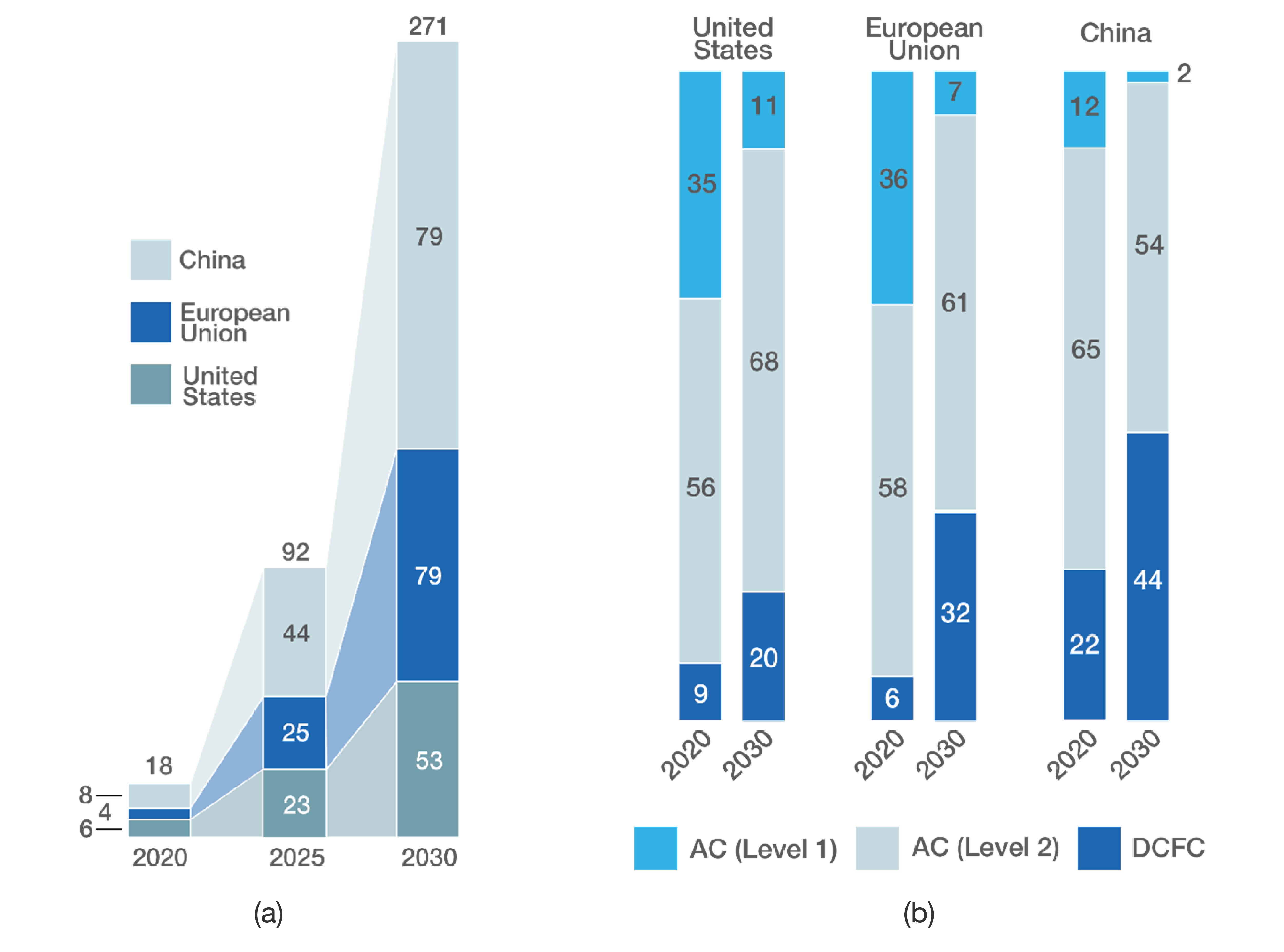
The demand for electric vehicles (EVs) worldwide has exploded in recent years, and market trends show this demand will keep increasing further. Thus, it is imperative that the proper energy availability and charging infrastructure are in place to support this mass adoption. Figure 1 presents the expected charging-energy demand for EVs across the globe. By 2030, the predicted yearly energy consumption of EV chargers is expected to reach 271 billion kWh, making it one of the main sources of global electric energy demand. This means that DC fast chargers (DCFCs) will place a tremendous amount of stress on the grid, so it will be essential to mitigate these risks to ensure a reliable, safe, and dependable power grid in the future.
Challenges | Impacts of DC fast chargers on the grid
Just as gas stations have more than one pump, multiple DCFCs are commonly installed at the same location to create a charging facility that can assist various drivers. However, unlike liquid fuels, electricity usually isn’t stored on site, which causes sharp peaks in power demand from the electrical grid. Furthermore, charging stations are frequently connected to low-voltage distribution systems that operate close to their maximum capacity, which can result in several energy quality issues.
When multiple EVs are connected to a DC charging station, the high current levels may cause voltage drops that can exceed standard limits. Thus, grid operation may be affected, and protection devices can trip. Moreover, installing DCFCs can result in voltage imbalance, flickering, harmonics, and other grid balancing issues, in addition to the conventional fault events that the grid is traditionally exposed to.
On the bright side, the abovementioned capacity of DCFCs to deliver high current levels can have a profound impact on solving grid imbalance issues when used at the right time. DCFCs should be designed to help restore the grid to regular operation after a fault and should provide fast ancillary services to help avoid faults from occurring in the first place. However, the thorough testing of DC fast chargers against grid faults and grid disturbances in the lab is complex, expensive, and raises safety issues due to high power level operation. This is where HIL solutions prove imperative in furthering the e-mobility movement.
Solution | Testing DC fast chargers against faults and grid disturbances with HIL
Typhoon HIL provides an end-to-end testing solution for assessing DCFCs against an endless number of real-world scenarios. By combining ultra-high fidelity real-time simulations and automated testing, our vertically integrated HIL solution helps with mitigating risks early in the design cycle, by identifying unforeseen challenges safely in a virtual environment. HIL solutions are ideal for rapid control prototyping of new DCFCs that are aligned with the standards, such as IEC 61000, and test cases, such as those described in UL 2231-2, that will be used to evaluate DCFC performance.
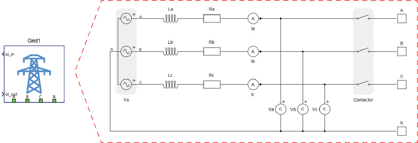
One of these tests is related to grid voltage dips, which can last several seconds and affect a single or multiple phases. To replicate these events, Typhoon HIL provides the Grid component, shown in Figure 2, which can be used to control the grid voltage dynamically. Therefore, engineers can ensure that the DC link and the output voltage of the DCFC will remain within acceptable limits throughout the duration of the disturbance, regardless of which phases are affected.
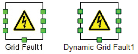
In case of voltage fluctuation and imbalance events caused by grid faults, tests should assess the current draw in addition to evaluating the charger DC link and output voltage. Typhoon HIL provides the Grid Fault and Dynamic Grid Fault components, shown in Figure 3, to replicate these faults. These components use ideal switches to emulate faults, and let you define the fault type and resistance.
Grid outages and interruptions are a more severe fault event type, and in their case, DCFCs are expected to normalize operation after the grid is restored. To test against these faults, engineering teams can select a variable outage duration using the controlled contactor to evaluate DCFC behavior during these interruptions.
Standards also define acceptable limits for the frequency and rate of change of frequency (RoCoF). DCFCs should operate adequately within these limits. Therefore, by changing the frequency of the Grid component, engineers can perform tests to ensure the phase-locked loop (PLL) will be ensured and the current drawn, Total Harmonic Distortion (THD), and DC link voltage will not exceed defined limits.
With Typhoon HIL, you can extensively test DCFC controllers for numerous complex scenarios and replicate them in the lab. Count on our team for support and take advantage of high-fidelity simulations and test automation to drive your way toward an electrified future.
Credits
Text | Cassiano F. Moraes, Heitor J. Tessaro
Visuals | Typhoon HIL Documentation, Karl Mickei
Editors | Juliano Grigulo, Sergio Costa, Debora Santo
