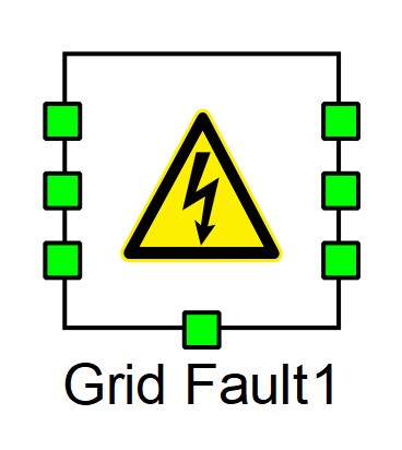
Grid Fault
Description of the Grid Fault component in Schematic Editor Library

Description
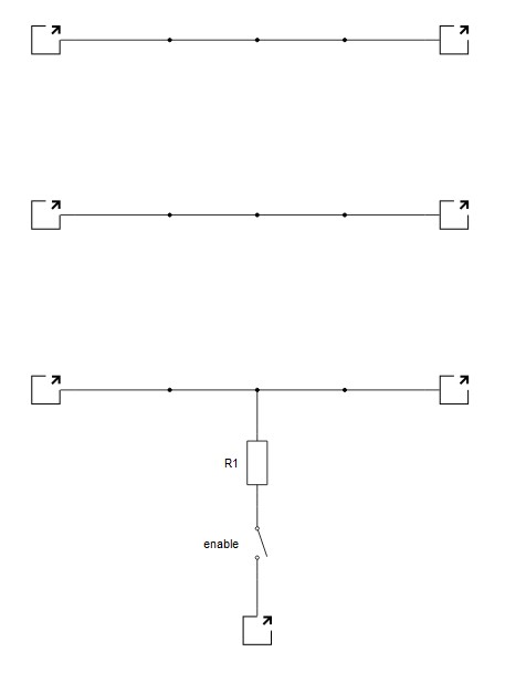
The Grid Fault component emulates a fault on a three phase grid using ideal switch. The fault type can be chosen by selecting one of the eleven fault types in a combo box in the Properties window of the component. A fault resistance can be defined; by default it is zero. Depending on the chosen fault type, the internal structure of the component is changed and an ideal switch is placed according to a chosen fault type. Based on chosen control source, the internal switch is controlled either from the internal structure, if the model is selected, or by chosen digital input. The internal structure of grid fault for C-N fault is shown in Figure 2.

List of available digital feedbacks of the grid fault is shown in Internal digital measurements of the Grid Fault.
Internal digital measurements of the Grid Fault
| Digital output variable name | Description |
|---|---|
| (name).enable.feedback | Digital feedback of the internal switch. |
Ports
- A1 (electrical)
- Left AC side port - phase A
- B1 (electrical)
- Left AC side port - phase B
- C1 (electrical)
- Left AC side port - phase C
- A2 (electrical)
- Right AC side port - phase A
- B2 (electrical)
- Right AC side port - phase B
- Right AC side port - phase C
- GND (electrical)
- Available if property Fault Type is set to A-GND, B-GND, C-GND, A-B-GND, A-C-GND, B-C-GND or A-B-C-GND.
- Ground point port
Parameters
- Fault resistance
- Specifies overall resistance of the fault.
- Fault type
- Defines required fault type.
- Available fault types are: A-GND, B-GND, C-GND, A-B, A-C, B-C, A-B-GND, A-C-GND, B-C-GND, A-B-C, and A-B-C-GND.
- Control source
- Choose if the internal contactor is controlled by a digital input signal or through a signal from the model.
- Sa
- Internal contactor gate signal digital input channel address: Sa(1..N).
- Sa logic
- Internal contactor gate logic (active_high or active_low).
- Feedback output
- Enable internal contactor feedback Signal Processing output.
- Signal type
- Internal contactor feedback signal type (int default).
- Execution rate
- Signal Processing execution rate