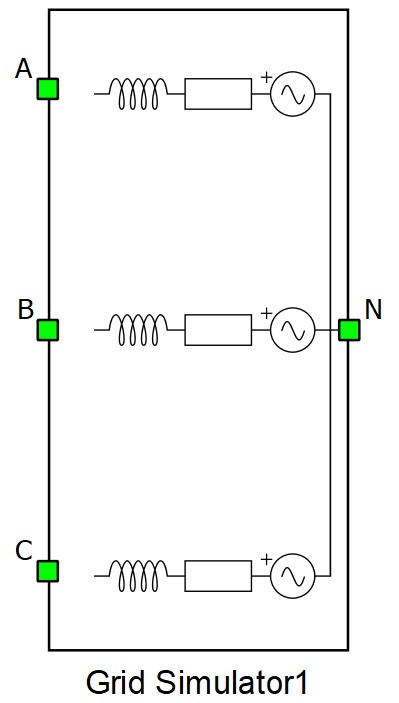
Grid simulator
Description of the Grid Simulator component in Schematic Editor
The Grid Simulator is a component which consists of three single phase voltage sources, series resistances and inductances. It is used to simulate a three phase symmetric or asymmetric grid.
The internal structure of the Grid Simulator, with phase voltage, line voltage and phase current measurements included is shown in Figure 2.
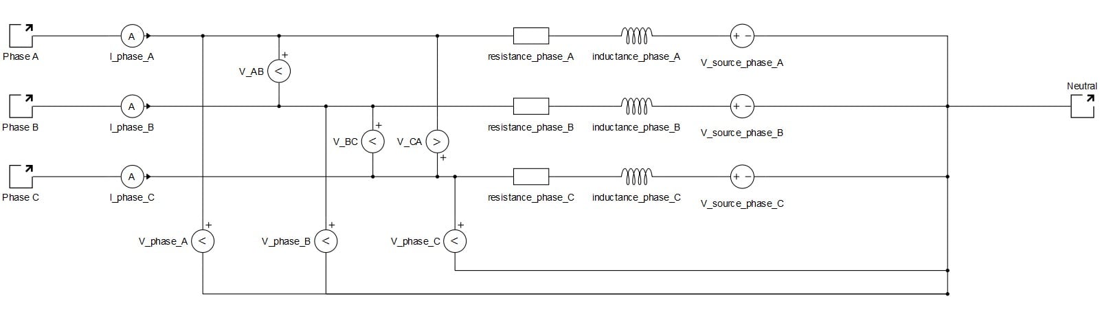
The list of measurements available in the grid simulator is shown in Internal analog measurements of the grid simulator.
Calculation from S-U to R-L
Calculation from S-U and X/R to R-L
- R - resistance
- L - inductance
- Vb - nominal line voltage
- f - frequency
- Sb - short circuit capacity
- pf - inductive power factor
- X/R - x/r ratio
Internal analog measurements of the grid simulator
| Analog output variable name | Description |
|---|---|
| (name).I_phase_A | Phase A current. |
| (name).I_phase_B | Phase B current. |
| (name).I_phase_C | Phase C current. |
| (name).V_phase_A | Phase A voltage. |
| (name).V_phase_B | Phase B voltage. |
| (name).V_phase_C | Phase C voltage. |
| (name).V_source_phase_A | Phase A source voltage. |
| (name).V_source_phase_B | Phase B source voltage. |
| (name).V_source_phase_C | Phase C source voltage. |
| (name).V_AB | A-B line voltage. |
| (name).V_BC | B-C line voltage. |
| (name).V_CA | C-A line voltage. |
Ports
- A (electrical)
- AC side port - phase A
- B (electrical)
- AC side port - phase B
- C (electrical)
- AC side port - phase C
- N (electrical)
- Neutral point port
Parameters
- Model definiton
- Specifies the set of parameters by choosing between R-L, S-U, and S-U and X/R.
- Nominal line voltage
- Specifies nominal line voltage.
- Nominal frequency
- Specifies nominal frequency.
- Resistance per phase
- Available only if Model definition is set to R-L.
- Specifies resistance per phase.
- Inductance per phase
- Available only if Model definition is set to R-L.
- Specifies inductance per phase.
- Short circuit capacity
- Available if Model definition is set to S-U or S-U and X/R.
- Specifies short circuit capacity.
- Inductive power factor
- Available only if Model definition is set to S-U.
- Specifies inductive power factor.
- X/R ration
- Available only if Model definition is set to S-U and X/R.
- Specifies ratio between X and R values.