Anti-islanding Container
Description of the Anti-islanding Container component in Schematic Editor.
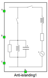
The Anti-islanding Container component is composed of three phase switches, three phase voltage source, passive components, and measurements. The internal structure of the anti-islanding container is shown in Figure 2. Phase voltage and phase current measurements are included, as shown in Figure 2.
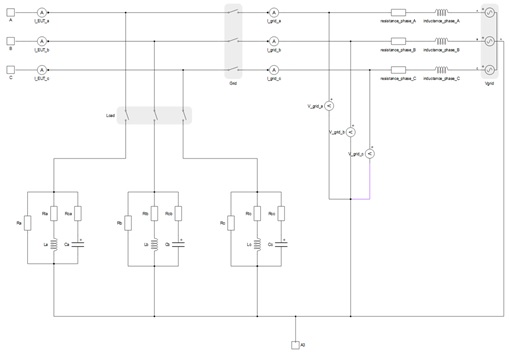
The list of available measurements of anti-islanding is shown in Table 1.
| Analog output variable name | Description |
|---|---|
| (name).I_EUT_a | Phase A current of device under test. |
| (name).I_EUT_b | Phase B current of device under test. |
| (name).I_EUT_c | Phase C current of device under test. |
| (name).I_grid_a | Phase A grid current. |
| (name).I_grid_b | Phase B grid current. |
| (name).I_grid_c | Phase C grid current. |
| (name).V_grid_a | Phase A grid voltage after grid impedance. |
| (name).V_grid_b | Phase B grid voltage after grid impedance. |
| (name).V_grid_c | Phase C grid voltage after grid impedance. |
| (name).Vgrid_A | Phase A grid source voltage. |
| (name).Vgrid_B | Phase B grid source voltage. |
| (name).Vgrid_C | Phase C grid source voltage. |
| (name).inductance_phase_A | Phase A grid inductance current. |
| (name).inductance_phase_B | Phase B grid inductance current. |
| (name).inductance_phase_C | Phase C grid inductance current. |
| (name).La | Phase A RLC load inductance current. |
| (name).Lb | Phase B RLC load inductance current. |
| (name).Lc | Phase C RLC load inductance current. |
| (name).Ca | Phase A RLC load capacitance voltage. |
| (name).Cb | Phase B RLC load capacitance voltage. |
| (name).Cc | Phase C RLC load capacitance voltage. |
Ports
- A (electrical)
- AC side port - phase A
- B (electrical)
- AC side port - phase B
- C (electrical)
- AC side port - phase C
- N (electrical)
- Neutral point port
Parameters
- Resistance of the RLC load (per phase)
- Specifies resistance of the RLC load per phase.
- Inductance of the RLC load (per phase)
- Specifies inductance of the RLC load per phase.
- Capacitance of the RLC load (per phase)
- Specifies capacitance of the RLC load per phase.
- Resistance of the Grid (per phase)
- Specifies resistance of the grid load per phase.
- Inductance of the Grid (per phase)
- Specifies inductance of the grid load per phase.