Introduction | Power electronics controller testing made safe
There are several ways to approach controller firmware development and testing for power electronics (PE) applications. When this is done for academic teaching purposes, it is essential that the chosen approach allows for students to learn from their mistakes while gaining valuable hands-on experience with personal and equipment safety ensured. For these reasons, software-in-the-loop (SIL) and controller-hardware-in-the-loop (C-HIL) are often the methodologies of choice for rapid control prototyping (RCP) in academic and industrial environments alike. Working in a simulated real-time environment allows for observing control behavior in diverse scenarios with the safety of students and equipment guaranteed since power flows are represented digitally instead of physically.
Solution | Infineon and Typhoon HIL integration for EV testing
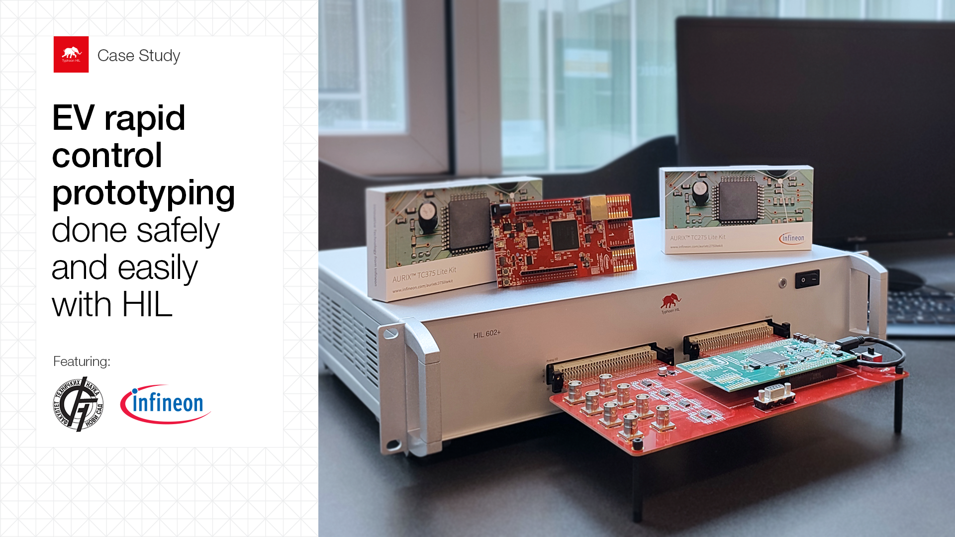
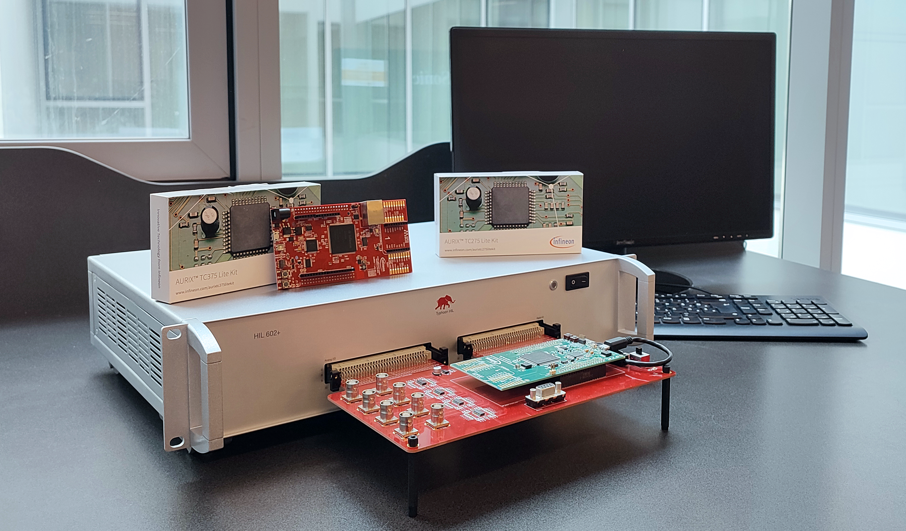
The setup is integrating solutions of two companies, Infineon Technologies and Typhoon HIL (see hardware setup in Fig. 1). It consists of an emulator (Typhoon HIL HIL602+ real-time device), a custom interface board built by Typhoon HIL, paired with a controller from Infineon Technologies (AURIX™ TC275 Lite Kit or AURIX™ TC375 Lite Kit, for example), and a PC.
The setup specifications definition, integration, and examples development were done by Dr. Ivan Todorovic for educational use with his students at The Faculty of Technical Sciences of the University of Novi Sad, Serbia.
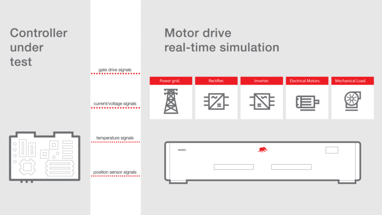
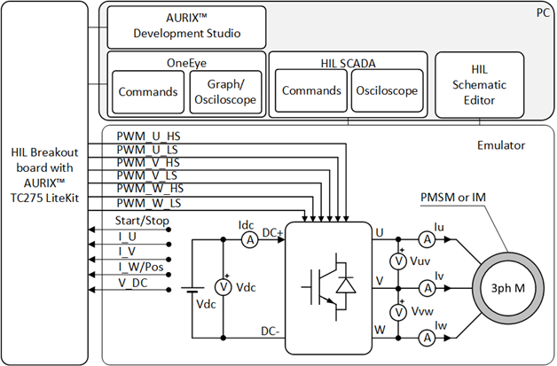
The power electronics power stage is modelled and executed in real-time on the HIL602+ device through the Typhoon HIL Control Center, the interface board adjusts analog and digital signals exchanged between the emulator and the controller, while the controller is programmed using AURIX™ Development Studio and the internal variables are observed using OneEye graphical user interface. A representation of a C-HIL platform setup for the development and testing of EV applications is shown in Figure 2.
Learn more | Setup versatility and easy adoption by students
We are inviting you to learn more about this setup on the original blog published on Infineon’s website. You will find more detailed descriptions, additional figures, as well as further information on how this setup works.
Credits
Text | Original text by Emna Azek, adapted by Debora Santo
Visuals | Setup photo and figure provided by Ivan Todorovic, blog cover image by Karl Mickei
Editor | Debora Santo
