Introduction | Digitalization plus Electrification equals Microgrid
You hear “digital” a lot when you go to shows like ASNE’s “Intelligent Ship” or the “Navy League’s Sea Air Space Exposition.” Computing requirements, cyber considerations, model-based diagnostics, autonomous control for unmanned vehicles, etc. are all the rage.
It’s also clear that ships are becoming increasingly reliant on electric power to run the computers required for digitization and propulsion, sensors, thermal control, electromagnetic catapults, and directed energy applications.
These two concepts – digitization and electrification – should not be considered separately. You cannot run computers without high-quality electricity. You cannot scan with a phased array radar without tremendous power, for short bursts, at irregular times.
You’re constrained by efficiency and size requirements. And at some juncture, demand for power will exceed generation capacity.
You are also going to have equipment degradation over time.
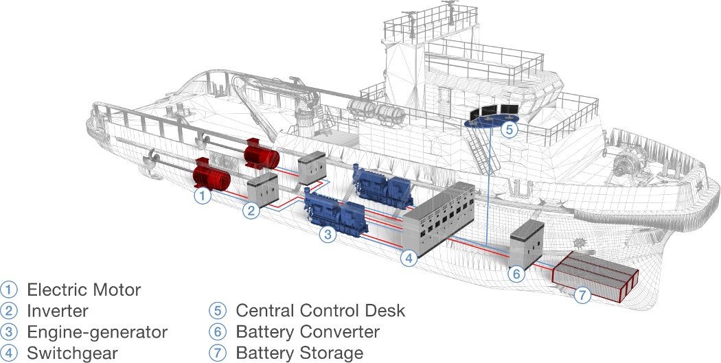
So why not put the two thoughts, digitization and electrification together?When Distributed Energy Resources (gensets and storage) are connected to loads and the system is controlled by computers, you have a microgrid.The ship is a microgrid.
Why is designing and building a microgrid so hard?
Two reasons: speed and volume – both are related to digital control of electricity.
Challenge 1 | Let’s start with speed.
No engineer tasked with designing and building a ship today would consider doing so without 3D CAD/CAM. An amphibious ship is modeled in detail using computers, from the piping to passageways. The mechanical model is subsequently packaged to allow one yard to build the aft section of the vessel, while another builds the forward section.
Before any steel is cut and laid, engineers run simulations on the model to ensure specifications are met.
Designers are able to “walk” a six-foot model “test subject” through every passageway in the ship. The software automatically takes notes when our digital Marine bumps his or her head on an overhead or runs into other models during drills simulating the entire crew, etc.
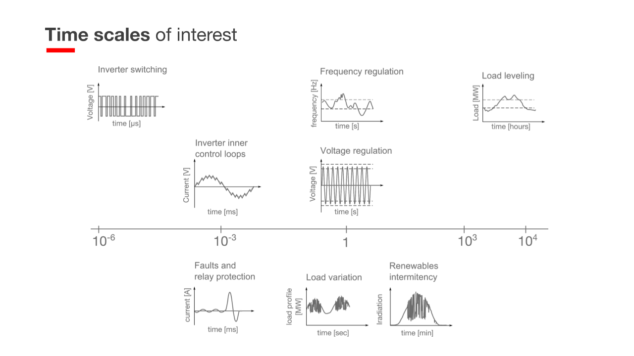
This Model-Based Engineering (MBE) approach saves millions when problems requiring design modification are detected well in advance of construction. But what about when tests and simulations require our six-foot tall “test subject” to represent electricity or control signals?Let’s say you have millisecond fidelity, then you’ll miss the “test subject” altogether or, if you luck out and see him, you won’t know for certain if he hit his head a 900 times before or 153 times afterward.
In order to catch our electronic “test subject” hitting their “head” on an electronic “overhead” (for example a Static Automatic Bus Transfer (SABT)), or the interactions between generation and loads, one has to be able to observe interactions occurring at the speed of electricity – essentially inside of a microsecond.That’s fast!
If you don’t have that speed, you have to build a full-scale prototype. And that’s not a guarantee that it will work, but is guaranteed to cost a lot of money.
Challenge 2 | Volume is the next problem.
Consider relays onboard the ship. What used to be manual switches are now computerized. The device itself has a controller and it is in turn controlled by a remote station or multiple system controllers. As more and more devices aboard ships have computer controllers embedded, the so-called Internet of Things comes to mind, the ship becomes digitized.
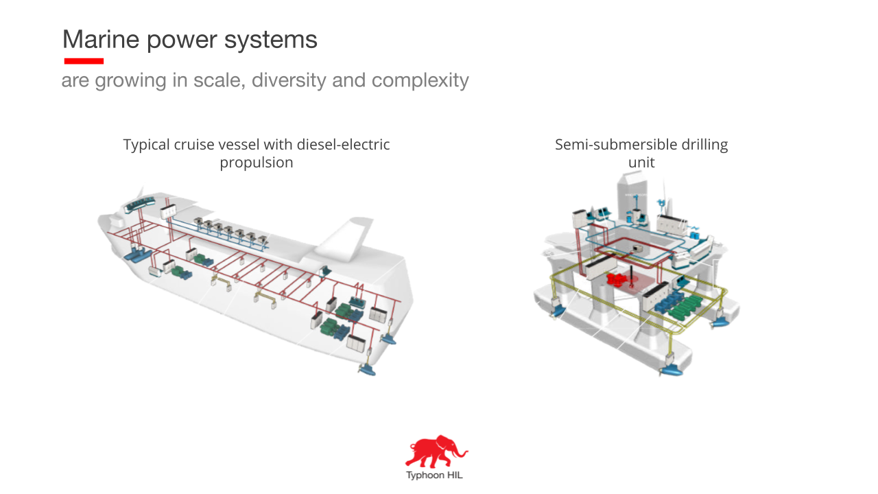
Now consider lines of code in each of these “smart” devices.
Thousands even hundreds of thousands of lines are the norm. Now multiply by thousands of devices and throw in different vendors / software engineers.
How do you manage this volume of code and the interactions between all those controllers?Let’sconsider a firmware update on our “smart” controller. How do you know that a single update won’t damage the whole system?
Solution | Why Controller Hardware-in-the-Loop (C-HIL) for MBE?
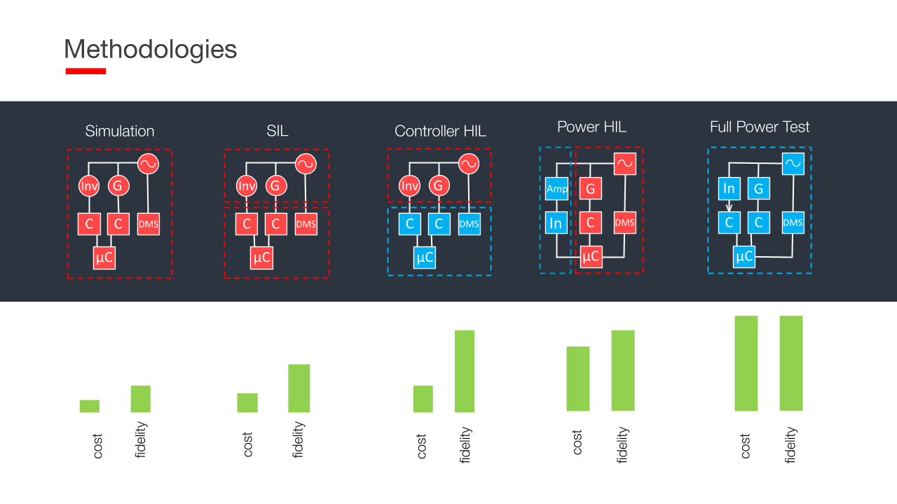
To verify and validate controllers and firmware updates, a C-HIL platform allows for extensive testing to ensure microgrid controller performance. The Typhoon ultra-high fidelity C-HIL system is a hardware, software, and engineering services package that empowers system integrators.
Our MBE approach focuses on the complex interaction of power systems and controls that comprise a modern microgrid.
To achieve the real-time (sub-microsecond) fidelity required in this power electronic and control space, actual digital controllers are integrated with digital models in a Controller-Hardware in the Loop (C-HIL) testbed.
Benefits | Supercharge Ship Lifecycle Maintenance with C-HIL
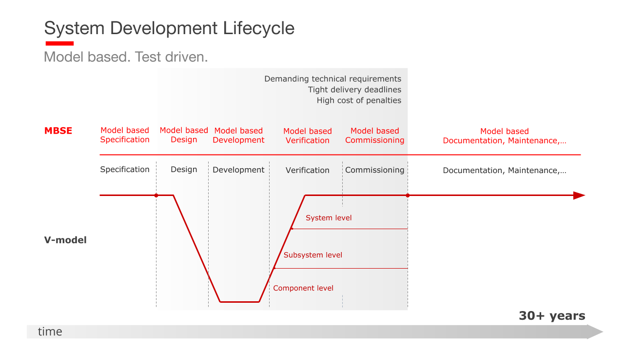
The Typhoon C-HIL Testbed can be used throughout the lifecycle of the project as a tool to refine the concept. This real-time simulation platform provides a very high-fidelity microgrid digital twin which allows ship power system designers to:
- Seamlessly test firmware and software upgrades to smart devices and microgrid controllers before deployment;
- Model and simulate anomalies that may be anticipated or discovered during operation, and test fixes;
- Test equipment upgrades and any interoperability issues that might arise prior to deployment;
This approach reduces risk, saves time and money, and enhances operational effectiveness and resiliency over the entire lifetime of the project.
Credits
Author | Matt Baker
Visuals | Karl Mickei
Editor | Debora Santo
