Introduction
The increasing adoption of Distributed Energy Resources (DERs) – Photovoltaic (PV) systems, battery energy storage systems (BESS), wind generators, fuel cells, etc. – is driving the need to coordinate and control these assets effectively in the electric power grid.
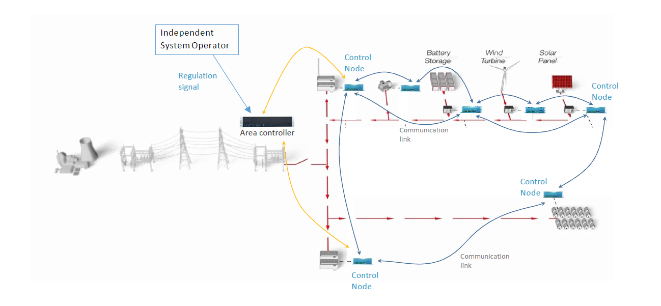
Under the previous ARPA-E Network Optimized Distributed Energy Systems (NODES) program funding, researchers from the University of Illinois at Urbana Champaign (UIUC) developed an architecture for distributed control and coordination of DERs within a microgrid for the provision of frequency regulation (Fig. 1 below).
Project Goal
In collaboration with Typhoon HIL and the Missouri University of Science and Technology (MS&T), the goal of the current ARPA-E NODES project is to further de-risk the distributed control architecture by tightly integrating the control algorithms used for distributed decision-making. And implementing them onto a Typhoon HIL Controller Hardware-in-the-Loop (C-HIL) microgrid testbed.
Olaolu Ajala, a research engineer at the Grainger College of Engineering at UIUC, shows how this distributed microgrid controller architecture works using the Typhoon HIL microgrid testbed (below).
C-HIL Testbed | Cyber Layer
The C-HIL microgrid testbed comprises a cyber layer and physical layer used for the coordination of DERs – two rooftop solar PV units, one fuel cell unit, and one battery storage unit.
Cyber layer controllers carry out the distributed control algorithms to reach a consensus on the control action and provide the frequency regulation ancillary service provided by the PJM regulation market.
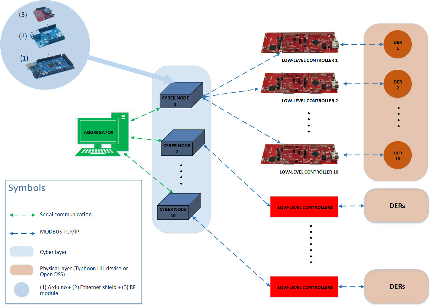
The cyber layer (Fig. 2 above) consists of an aggregator and control devices interconnected over a communication network. Each control device in the cyber layer is connected to and controls a DER in the physical layer. The cyber layer is implemented in hardware using these devices: a computer, microcontrollers, and an Xbee-based wireless communication network. Each of the control devices is connected to a DER in the microgrid through cat6 cables using the ModBus TCP communication protocol (Fig.3 below).

The cyber layer performs three major tasks:
- Determines the required change in total generation in the microgrid
- Computes the optimal contribution of each DER to the required change in generation
- Locally controls each DER to change its generation accordingly
The distributed communication and control architecture implemented in the cyber layer creates an architecture that is robust against communication link failures.
C-HIL Testbed | Physical Layer
The physical layer consists of a microgrid interconnected to a bulk power grid through a set of tie-lines. The microgrid has inverter-interfaced DERs with each controlled to deliver specified real power and reactive power injections to the system.
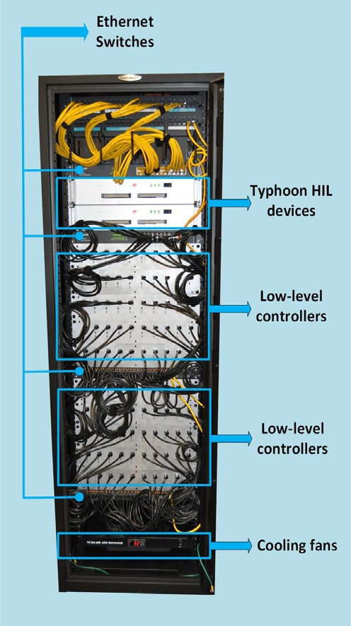
Typhoon HIL 6 series was utilized for real-time emulation of the physical layer. The emulators with the Typhoon HIL Control Center software toolchain are equipped with detailed and reduced models of:
- PV panels
- Batter Energy Storage Systems
- Wind Turbine Generators
- Microturbines
- Fuel Cells
- Loads
Field Testing at MS&T
The Solar Village built at Missouri S&T was used for field testing the above-described distributed control architecture setup. The Center for Research in Energy and Environment (CREE) manages the Village, and performs, among others, research in cyber security, sustainable energy research, and big data analytics.
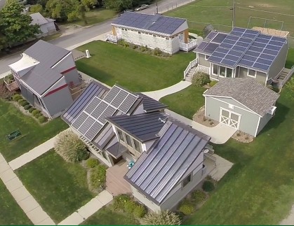
Each home has a 21kW PV panel with a Fronius grid-tied inverter that connects it to a common microgrid. A 5 kW natural gas fuel cell applies the aspects of heat and power to the microgrid. This setup directs energy firstly to loads and then allows for the excess energy to be directed either to storage or the municipal grid. The time of use, demand response, and load shifting scenarios will be implemented to observe how they affect microgrid power operations.
Expected Benefits
With orders of magnitude improvements in resilience and scalability, the distributed control approach will satisfy the performance metrics that are necessary for the effective provision of frequency regulation services.
Summary of the advantages of C-HIL and Model-based Design applied in this project:
- Model Integration Facilitates forward/backward mobility in the design process
- Co-simulation and Hardware-in-the-Loop expose realistic interactions
- Automation (“wizards”) refocus engineering efforts toward understanding and improvement
- Result: expedited deployment of advanced technologies with reduced risk
Credits
Author | Samantha Bruce, Debora Santo
Visuals | UIUC
Editor | Debora Santo
