Introduction
Using a Controller Hardware-in-the-Loop simulation platform, EPC Power was able to integrate its control software with new hardware in just two days.
Based in San Diego, CA, EPC Power designs and manufactures grid-forming bi-directional inverters and DCDC converters for solar, wind, energy storage, automotive, and microgrid applications.
Ryan Smith, Chief Technology Officer (CTO) and Chief Controls Architect, talks about his experience using Controller Hardware in the Loop (C-HIL) from the early conceptual stage to final product certification and lifecycle maintenance.
What major challenges do inverter manufacturers face when developing and testing MW-scale inverters?
One of the biggest challenges working with high-power inverters is that there’s very little room for error. The price of failure with one of these high-power inverters is high. Both in material costs and hazards to customers and even adjacent equipment. So it is important that the inverters are tested to the extreme in our lab before they go out. Even above and beyond what’s required by the safety certifications.
How did you design and test inverter controllers before using Hardware-in-the-Loop?
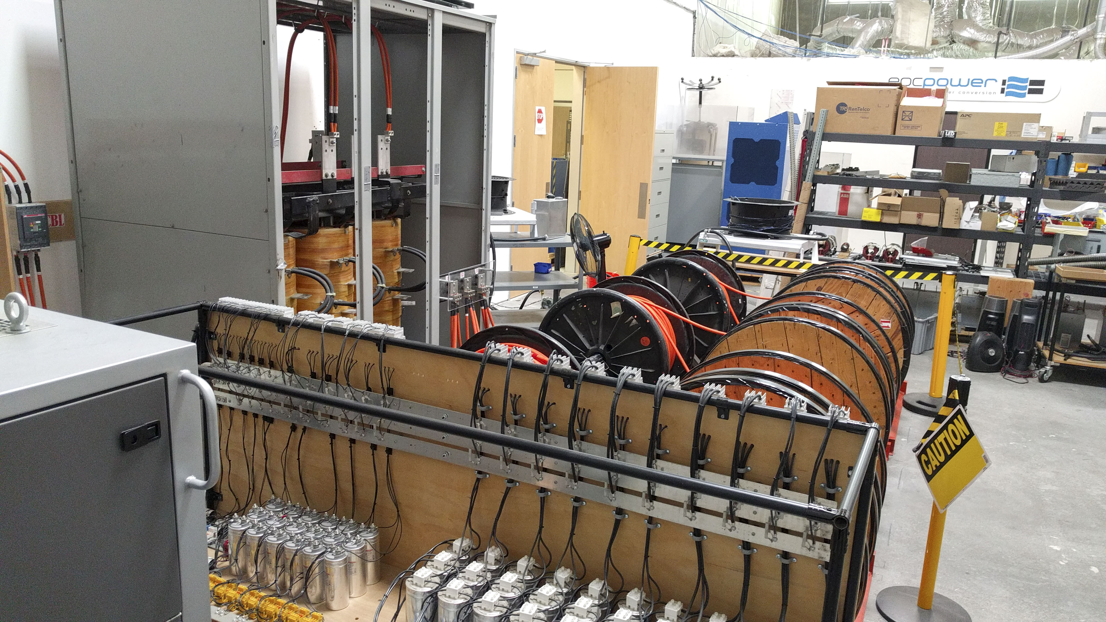
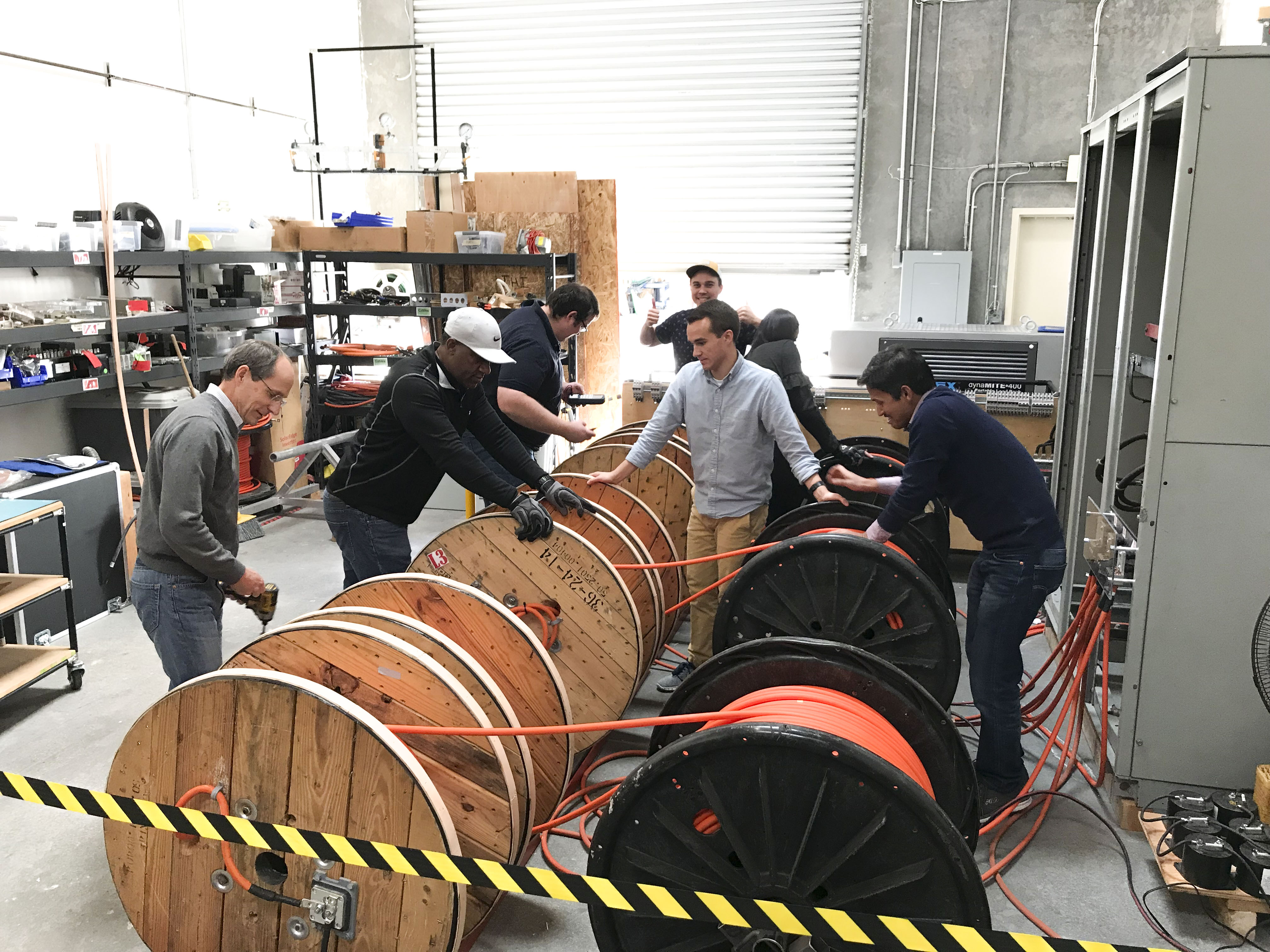
Before we started using a Hardware-in-the-Loop simulator, we tested the inverters using the equipment available in our power test lab. It’s a large power setup with high-power batteries and a high-power grid connection. We would then test inverters in a back-to-back configuration using a grid simulator in some cases. It’s expensive equipment that’s difficult to reconfigure. And it could sometimes take a day or two to set up to run a specific test.
What’s a better way of testing inverter controllers?
Since we’ve adopted a Hardware-in-the-Loop simulator, a much better way to test the inverter is to test the controller against simulated hardware. The advantages of doing that are not just efficiency but we can run a test with a Hardware-in-the-Loop simulator much more quickly than we could in the lab.
We can also test in a wider variety of scenarios than we can even simulate in a lab environment. So it’s more extensive testing as well as more efficient testing.
How does a HIL environment compare to a full power lab when developing your inverter controllers?
Test time in our power lab is very expensive. We only have one full power test available and it really takes a couple of people to run it full time. It’s not a good development environment. It’s more of a validation environment.
Typhoon HIL makes a much better control development environment because you can try new things. You can also attempt operational scenarios that are difficult to simulate in the lab. And you can do that very quickly.
What tests can you do more easily with Hardware-in-the-Loop that is difficult to test in a power lab?
We specify to our customers a maximum grid impedance of 8% and then expected to operate down to an ideal grid impedance. That’s difficult to simulate in a lab where you have a fixed grid impedance. But we’re able to test across a range of grid impedances with the Hardware-in-the-Loop simulator. As well as outside that range for specific customers that have an especially weak grid.
What is the biggest advantage of using this platform?
The biggest advantage that we’ve seen is the acceleration that it has afforded our design team. Before we started using it, software had always been the bottleneck in our product development cycle. The reason for that is usually because the software and controls team are handed the hardware at the end of the design cycle and then asked to make it work.
By using a Hardware-in-the-Loop simulator, the controls design team can work in parallel to the hardware design team so that the hardware and the controls mesh at the end.
It’s a very simple integration step to get new hardware running. We’ve been using it for the last two design cycles and we’ve seen a massive improvement in the speed of the integration phase.
Can you give an example of how HIL shortened EPC’s development timeline?
One example is when our 500kW inverter was first made available to the controls team. The controls team had been working for maybe two months using the Hardware-in-the-Loop simulator.
When that control software was loaded in the hardware, in less than two days, it was running at full power. Before using Hardware-in-the-Loop simulation, we would typically scope for maybe six weeks.
So it’s significant savings for a small company like ours to shave that much time off the development timeline.
So how did you set up your HIL for testing?
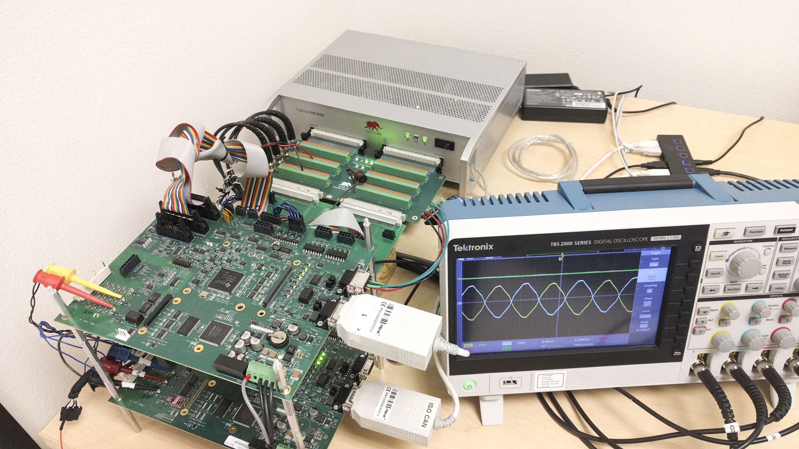
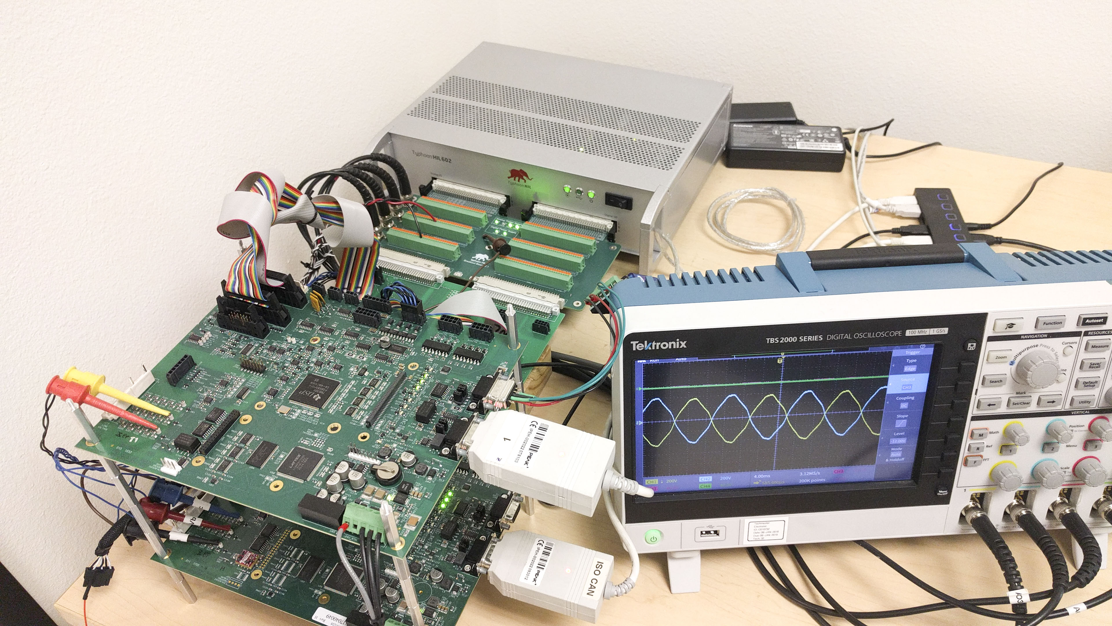
We use the Typhoon HIL602 Hardware-in-the-Loop simulator. And that interfaces through a breakout board to our controller. It’s the same control board that we use in our product based on a DSP from Texas Instruments. The control board runs the exact same software in a real inverter. We don’t have any conditions that are imposed on it that allow it to know that it’s in a Hardware-in-the-Loop simulation environment. So we get the exact representation of parameter scaling and measurement ranges from this test platform.
What are the biggest advantages of using HIL at the early stages of development?
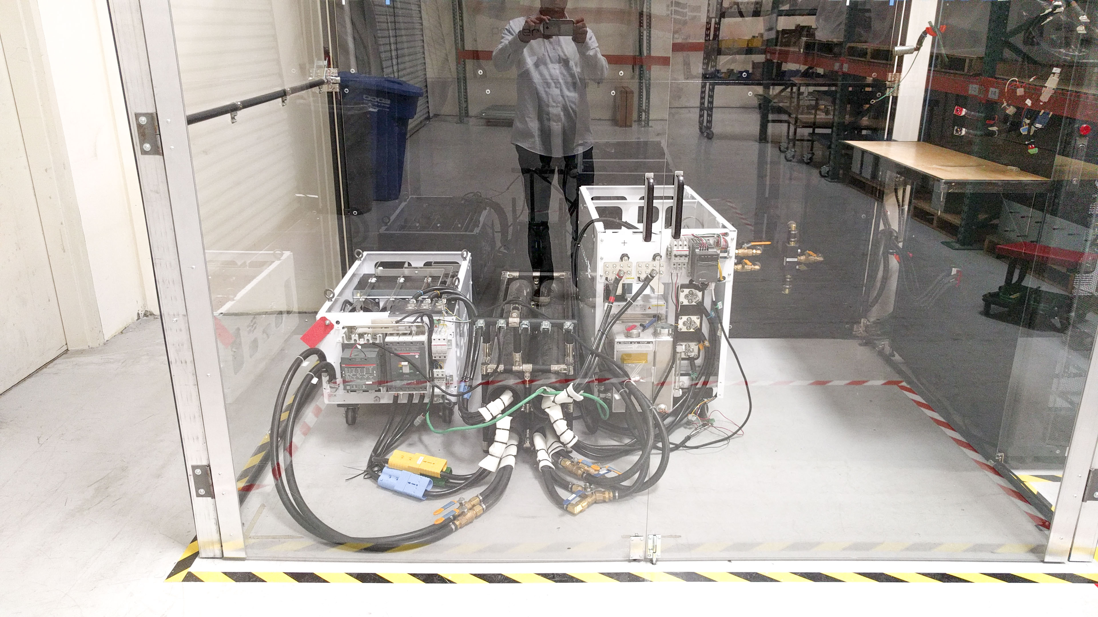
The risks are a lot lower for hardware when you make a mistake in the control software. There isn’t a big explosion behind the glass. So that’s probably the biggest advantage. But it’s also much easier to establish the test condition that you’re hoping to test against with the Hardware-in-the-Loop.
It’s also a lot easier to get control information back from the control board when you’re connected to a Hardware-in-the-Loop simulation because you don’t have the interference of high-voltage noise. So we’re able to use the JTAG interface to connect to the control processor and use a debugger. These are risky to use when you’re in a high-voltage high-power environment.
Can you give us a specific example of how you were able to troubleshoot a problem using HIL?
We were troubleshooting a resonance issue with the output filter of our inverter against a specific grid impedance. The resonance issue didn’t show up in the simpler simulations – just pure software simulations – but it did show up in the hardware.
When we had access to a Hardware-in-the-Loop simulator, it represented the same resonance that we had seen in a fielded application. And we were able to test strategies to mitigate that resonance. So when we zeroed in on a strategy and filled it, it did take care of the problem in the actual application.
How long does it take to run, say an anti-islanding test using HIL?
To run anti-islanding, the hardware-in-the-loop simulator takes literally a couple of minutes. It doesn’t take any time at all. We have worked with some of the scripting tools available.
We can set up and run an entire suite of tests just with one click. So we can run through all those tests in a matter of minutes.
And test different algorithms to check whether they have any holes in them.
You’ve recently completed UL1741SA certification for one of your inverters. Is that correct?
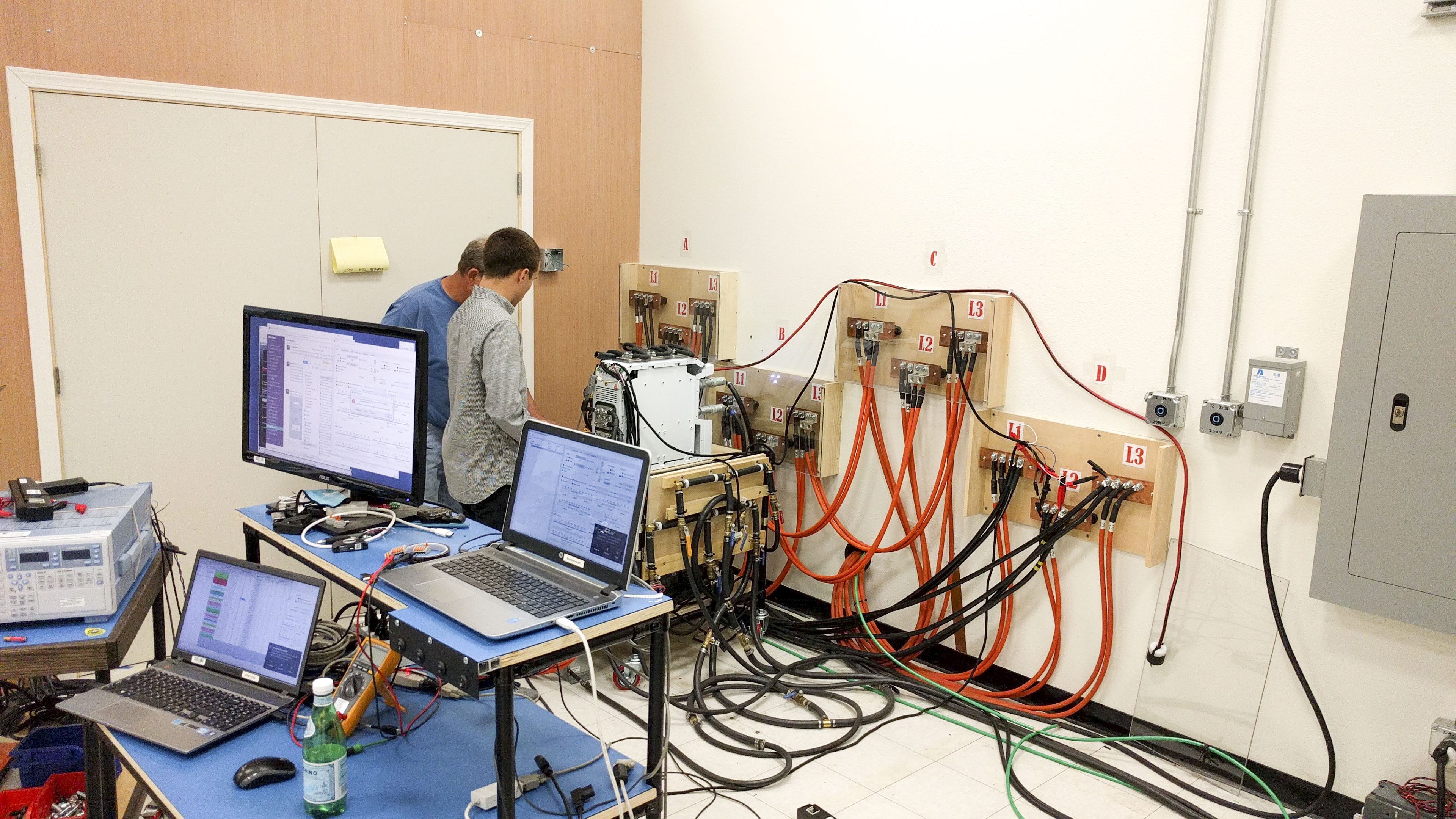
Yes, that is correct. We just completed certifying a 375kW inverter and we’re testing a 500kW inverter now. We have a 1 megawatt-hour lithium-ion battery on-site and a 500kW load bank. As well as inductive loads and capacitive loads to simulate the resonant conditions that are required. So it’s quite a lot of equipment and takes several hours to set up each test.
What test was the most difficult to do of EPC’s inverter controllers for UL1741 SA?
For smart inverters, one of the tests that are required during the certification process is anti-islanding. This probably takes most hardware in the power test lab. To create the island conditions that are required by the certification body, anti-islanding testing takes at least a third of the total test time for each certification cycle.
We have an entire bay full of equipment — loads and simulation loads–dedicated to that testing. We were able to develop the control algorithm that we used against the Hardware-in-the-Loop simulator before we constructed loads in the lab to perform the certification tests. When we did test it on actual equipment, we passed every test that we ran without having to rerun or modify the algorithm.
How long was the test cycle for UL1741SA certification?
The total test cycle was about six weeks. But prior to beginning certification testing, we had run all the tests on the hardware-in-the-loop simulation platform. So by the time the test representative was on-site at our power lab to do witness testing, it was just a matter of the setup time and test time. All the tests passed on their first run. However, because of the requirements of the UL standard, all the tests still must be run on actual hardware.
By the time you get to a customer site, you want to have good confidence in the controls that you’re running. We were able to do that by testing all the algorithms in the hardware-in-the-loop environment.
So we basically shortened the test cycle because it was just set-up, test, then tear down.
How easily can you make changes to firmware design and verify them after certification?
We’ve entered a quarterly re-certification cycle here at EPC where we run products through the UL test cycle to update features or to address issues. So the power test lab is almost totally consumed with testing to remain in that cycle. Using the hardware-in-the-loop simulator, we were able to test the next version of software sort of in parallel to one version being tested in the lab.
So by having the extra resources, it’s essentially like having several power tests labs available to the design team at any time.
How accurate are the simulation results?
Our experience so far has been that they’re extremely accurate. Even the cycle-by-cycle level current voltages are all represented exactly as they would be in real hardware. So very accurate yes.
How would you describe your experience with Typhoon HIL compared to other simulation platforms?
What I appreciate the most about the Typhoon Hardware-in-the-Loop platform is how easy it is to get up and running, and to model the hardware.
When I received our first Typhoon HIL602 for evaluation, I was able to represent our hardware and connect the control board in less than two days.
The second thing I like about the Typhoon Hardware-in-the-Loop simulator is the performance that we were able to get in the simulation of our hardware. To get the most accurate results, you want the simulation step size to be as short as possible or at least short enough that it’s negligible given the time step of your control algorithms.
The Typhoon HIL can simulate our circuit in about a one-microsecond time step without too much trouble. And if we really optimize it, we can get down to about half that.
One word to describe your experience with HIL?
I would say “surprised.” I was surprised by how much it’s benefited us and how much it’s reduced our workload and accelerated our development.
Credits
Author | Samantha Bruce
Visuals | EPC Power
Editor | Debora Santo
