Electric Motor Drives
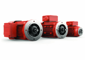

From electric vehicles (EVs) and electric trains, all the way to wind turbines and industrial automation, electric motor drives are accelerating the global shift to efficient and sustainable energy systems. As the advancements in technology continue to rise coupled with new environmental regulations, enabling manufactures and system integrators alike to simplify and speed up motor drives design and testing has never been more important.
High switching frequency converters, new wide-bandgap semiconductors, and new topologies are fueling the need for next generation controllers that are demanding Hardware-in-the-Loop (HIL) testing with ever smaller simulation time steps; faster gate drive sampling times; smaller loop-back latencies; and increasing model fidelity. With this added increased pressure surrounding enhanced product performance, functionality, and safety, unanticipated challenges must be discovered before costly errors occur.
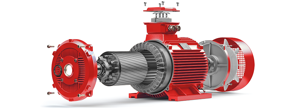
Typhoon HIL offers end-to-end solutions for electric motor drives, during the whole design cycle from Model-in-the-Loop (MIL) to Software-in-the-Loop (SIL) and all the way to Controller Hardware-in-the-Loop (C-HIL). Our tools and approaches help engineers effectively address challenges and ensure the reliability, performance, and safety of all motor drives systems.
Designed to streamline your efforts, our HIL simulators help you:
- Shorten test time, expediting you time to market to stay competitive
- Reduce development costs by testing early and often
- Revise test coverage for faults which are hard or impossible to replicate in the lab
- Enhance overall software quality by reducing the number defects and improve repeatability
- Develop project schedule performance with increased test coverage
- Model continuity across the whole software development workflow
Enhance your testing efficiency, effectiveness, and communication between your engineering hardware, software, and control design teams.
Explore our solutions that support even the most advanced motor drive applications today.
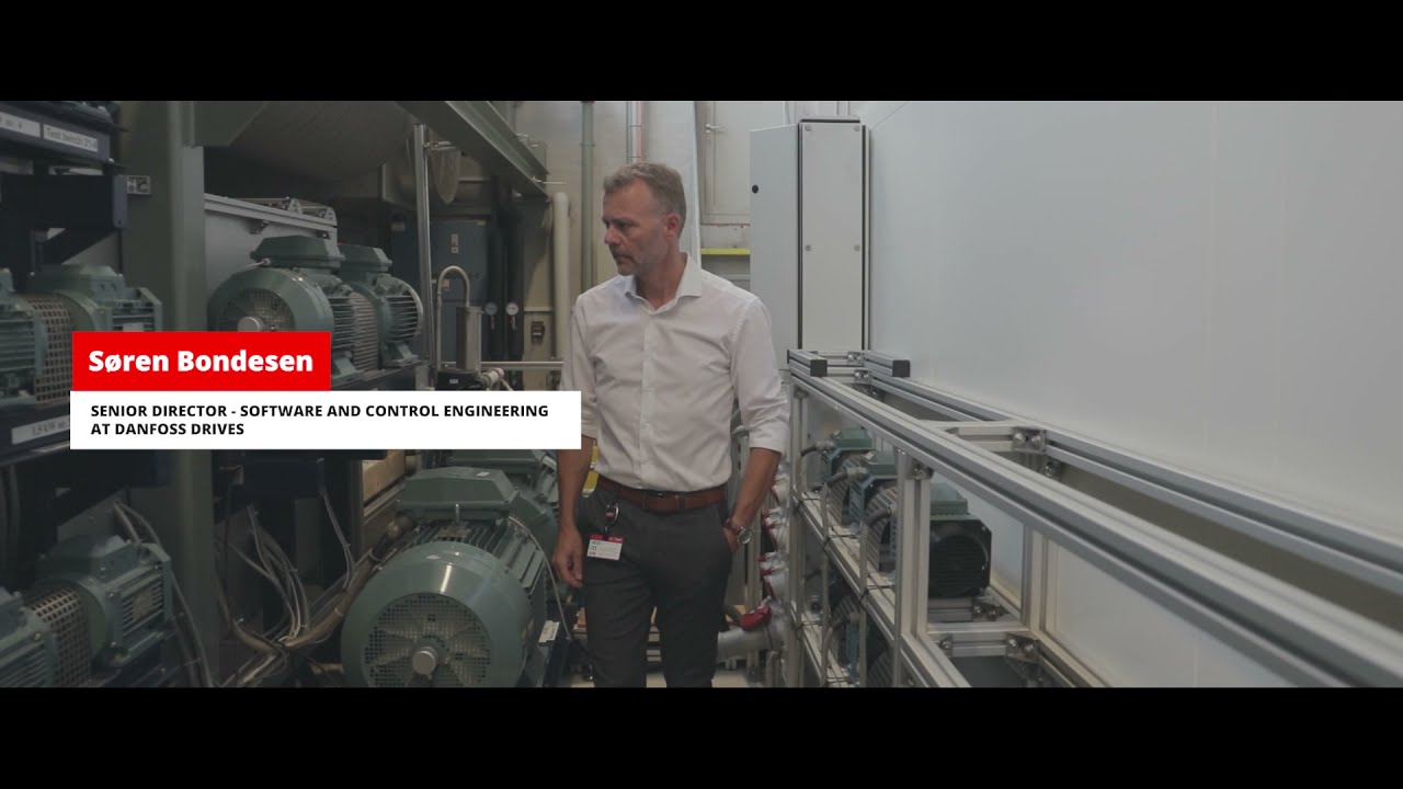

Danfoss Drives | Customer Support Speed and Drives Quality
In this first episode of the Danfoss Drives Spotlight Series, Søren Bondesen, the Senior Director of Software & Control Engineering at Danfoss Drives, describes how Typhoon Controller Hardware-in-in-the-Loop (C-HIL) technology increased customer support speed and drives quality.