


Introduction | The Rise of Solid-State Transformers
Solid State Transformers (SSTs) are replacing conventional copper-and-iron transformers with multi-stage power electronics, typically including an Active Front End rectifier, isolated resonant DC-DC converters, and an output inverter. This architecture enables active power management, bidirectional power flow, galvanic isolation, and seamless integration of distributed energy resources in a fraction of the size and weight.
But the same multi-stage complexity that makes SSTs powerful also makes them difficult to test. In this blog, we explore how Controller Hardware-in-the-Loop (C-HIL) simulation with Typhoon HIL enables engineers to validate complete SST control systems in real time, accelerating development while reducing risk.
Challenge | What Makes Testing SSTs So Challenging?
While C-HIL simulation is the natural path to validating SST controls, getting it right is far from straightforward.
- Multi-Stage Complexity: The AC-DC, isolated DC-DC, and DC-AC stages within the SST each carry their own controller, all of which must coordinate startup, voltage balancing, and power sharing with precise timing. A full system often exceeds the capacity of a single emulation unit, requiring multi-device setups connected through ultra-low-latency solver-to-solver links to maintain synchronization and simulation accuracy across the full model. Without sufficiently low latency between devices, the simulation risks becoming both inaccurate and numerically unstable, producing results that can no longer be trusted.
- Fidelity of Resonant Converter Simulation Controlled with High Switching Frequencies: Resonant converters equipped with a CLLC topology, increasingly built around SiC and GaN devices, routinely operate above 100 kHz and often well beyond. Accurately capturing switching transients and soft-switching behaviour at these frequencies demands extremely small simulation time steps at the resonant converter level. Many HIL platforms lack the processing capacity to maintain this resolution, forcing engineers to simplify the model, omit stages, or accept results that no longer accurately represent the real converter.
- Safe Fault Injection: At 10–50 kV, validating fault behaviour on physical hardware is not just costly, but dangerous. Shoot-through events, grid faults, and load transients must be tested in simulation, but many platforms lack stable fault injection support for the converter topologies that SSTs rely on. A solver that diverges mid-fault, or a platform that simply cannot simulate shoot-through on DAB and CLLC converters, leaves the most critical scenarios untested.
- Platform Workflow and Model-Building Effort: Building a full SST model on many HIL platforms is itself a significant undertaking, often requiring weeks of setup, FPGA and VHDL expertise that most control engineers don’t have, and hours of recompilation for even minor changes. For teams iterating on firmware, that overhead compounds quickly, narrowing test coverage and slowing development cycles. A HIL environment that is difficult to use will simply be used less, and the gaps in test coverage that follow are rarely visible until something fails in the field.
Solution | What Typhoon HIL Brings to SST Development
Typhoon HIL was built with power electronics complexity in mind. Where generic HIL platforms treat SST simulation as an edge case, Typhoon addresses it as a core use case. Each of the challenges above has a specific answer in the platform, instead of a workaround.
- Scaling Without Losing Accuracy: Typhoon HIL runs all SST conversion stages simultaneously on FPGA, with accurate interstage coupling and deterministic real-time behavior across the full model. When system complexity exceeds what a single emulation unit can handle, Typhoon’s High Speed Serial Link (HSSL) connects devices directly FPGA-to-FPGA, with solver-to-solver latency approaching a single microsecond and no CPU in the signal path. The full model scales from a single resonant converter stage to a complete multi-port SST within one consistent workflow, without compromising simulation accuracy or stability.
- Nanosecond Resolution for High-Frequency Converters: Typhoon’s UltraCore solver runs at a 3.5 ns time step, supporting switching frequencies well above 500 kHz and accurately capturing the fast dynamics of SiC- and GaN-based CLLC converters. Critically, these are mature, production-grade models available as drag-and-drop components, not recent additions that require custom VHDL knowledge to configure. Engineers get accurate resonant converter simulation without specialized FPGA expertise.
- Every Critical Fault Scenario, Tested Safely: Typhoon HIL supports shoot-through simulation on DAB and CLLC converters, as well as DC-side clamping faults, sensor faults, and open-circuit and short-circuit injection across all switching devices. These scenarios are programmatically triggered and fully repeatable, backed by a solver built to handle fault injection without diverging. Fault scenarios that would be dangerous or impossible to reproduce on physical hardware can be defined, executed, and iterated entirely in simulation.
- Less Time Building Models, More Time Testing: Typhoon HIL models are built through an intuitive drag-and-drop environment, with a mature component library covering all relevant SST topologies out of the box. No FPGA or VHDL expertise is required, and modifications and recompilation take minutes rather than days. The platform also exposes an extensive Python-based API, giving engineers full programmatic control over the simulation and enabling automated test campaigns covering parameter sweeps, fault injection sequences, and pass/fail verification at a scale that manual testing simply cannot match.
Conclusion | The Challenges, Reflected in a Real Model
The SST example model available in Typhoon HIL’s library (Fig.1) was not designed as a showcase. It is a working C-HIL demonstration of a 100-kVA SST topology, interfacing a 7.2 kV AC distribution grid with a 1 kV DC bus, and it runs against real control hardware: two Texas Instruments LAUNCHXL-F28379D microcontrollers connected to a HIL606 through the HIL TI μGrid LaunchPad Interface Board. The design decisions embedded in the model reflect exactly the challenges this post has described.
The power stage implements a single-phase, three-module Cascaded H-Bridge as the Active Front End, connected to the grid through a simple L-filter, followed by a Dual Active Bridge converter on each module. The outputs of the three DAB modules are paralleled to supply the DC load, with a low-pass filter at the output stage keeping the final voltage and current free of high-frequency ripple. The control is genuinely distributed: one DSP manages the entire AFE subsystem, regulating each CHB module’s DC link to 3.8-4 kV while maintaining unity power factor at the grid input, and the second DSP regulates the parallel output voltage to its SCADA-controlled setpoint of 1 kV while ensuring equal power is drawn from each module. The interstage dynamics are fully coupled in real time, which is precisely what makes it a meaningful test environment rather than a simplified stand-in.
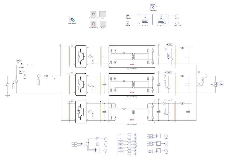
The DAB converters operate at a switching frequency of 100 kHz. At that frequency, accurate simulation depends on the nanosecond-range time resolution that the UltraCore cores provide, including support for the nonlinear inductor models that are essential for faithful representation of high-frequency transformer behaviour.
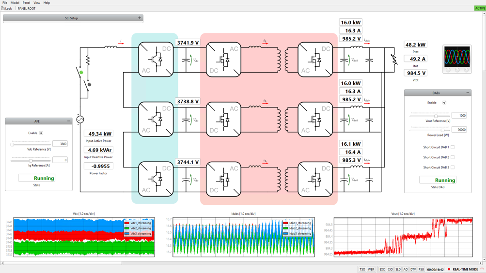
The model also includes a DAB short-circuit test, possible to trigger directly from the SCADA panel (Fig. 2): checking a single button short-circuits one leg of the selected converter, and the simulation remains stable through the event. It is a direct demonstration of shoot-through fault injection on a working high-frequency converter. The same panel exposes the Vdc reference and output load steps, and users are encouraged to go further, modifying the PI gains and plant parameters to explore the system’s stability margins and dynamic response under varying operating conditions.
One more detail worth highlighting is that none of the embedded code running on the two TI DSPs was handwritten. All of it is auto-generated using the newly released version 1.0.0 of the TI C2000 Toolbox, which translates the control algorithms modelled in the schematic directly into deployable code for the LAUNCHXL-F28379D boards. The controller being tested is, by construction, the same controller that was designed, eliminating the manual translation step where implementation errors typically creep in.