Three phase PLL
Description of the Three Phase PLL component in Schematic Editor, which generates output signals whose phase is related to the phase of an input three phase signal.
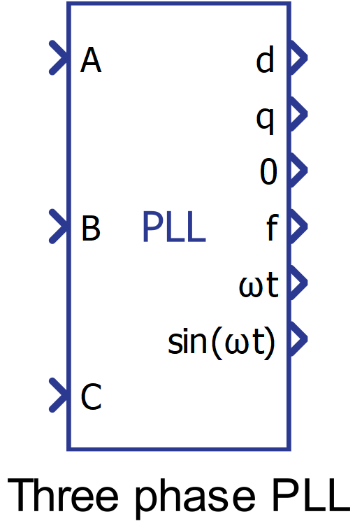
Component Icon
Description
The synchronous frame three phase PLL is widely used for tracking grid voltages and currents and for providing a synchronization signal to inverter based distributed resources.
A conceptual block diagram of the synchronous frame three phase PLL is shown in Figure 2.
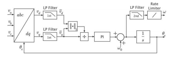
The abc-to-dq transformation makes use of the dq rotating reference frame in which the d-axis leads the q-axis. The end result is alignment of the d-axis with the peak of phase A in a balanced set (positive rotation).
The low pass filters remove noise and oscillations from the d and q-axes measurements.
The goal of the PID controller is to track the frequency, and phase of the three-phase input signal by forcing the q-axis component to zero through continuously adjusting the oscillator frequency (embodied by the integrator). An automatic gain controller estimates the amplitude of the input voltage which is then used to normalize the q-axis voltage.
Normalizing the input signal improves the PLL controller bandwidth by enabling it to track input signals with a wide range of amplitude variations.
A rate limiter and second order low pass filter are used to filter out noise and oscillations from the frequency measurement (in Hz).
Ports
- A (in)
- Input A related to the three-phase system whose phase and frequency is intended to
be extracted.
- Supported types: real.
- Vector support: no.
- Input A related to the three-phase system whose phase and frequency is intended to
be extracted.
- B (in)
- Input B related to the three-phase system whose phase and frequency is intended to
be extracted.
- Supported types: real.
- Vector support: no.
- Input B related to the three-phase system whose phase and frequency is intended to
be extracted.
- C (in)
- Input C related to the three-phase system whose phase and frequency is intended to
be extracted.
- Supported types: real.
- Vector support: no.
- Input C related to the three-phase system whose phase and frequency is intended to
be extracted.
- d (out)
- Output signal of the component related to the direct component of the abc-frame
input.
- Supported types: real.
- Vector support: no.
- Output signal of the component related to the direct component of the abc-frame
input.
- q (out)
- Output signal of the component related to the quadrature component of the abc-frame
input.
- Supported types: real.
- Vector support: no.
- Output signal of the component related to the quadrature component of the abc-frame
input.
- 0 (out)
- Output signal of the component related to the zero component of the abc-frame
input.
- Supported types: real.
- Vector support: no.
- This output is dynamically created when property enable 0 axis output (from dq0) is set to True
- Output signal of the component related to the zero component of the abc-frame
input.
- f/ω (out)
- Frequency of the three-phase input system. This value can be output as Hz or rad/s,
depending on the value set on the component’ parameter frequency output
unit.
- Supported types: real.
- Vector support: no.
- Frequency of the three-phase input system. This value can be output as Hz or rad/s,
depending on the value set on the component’ parameter frequency output
unit.
- ωt (out)
- Angle of the three-phase input system.
- Supported types: real.
- Vector support: no.
- Angle of the three-phase input system.
- sin(ωt) (out)
- Value of the trigonometric function ‘sin’ applied to the value of the phase of the
three-phase system.
- Supported types: real.
- Vector support: no.
- This output is dynamically created when property enable sin(ωt) output is set to True
- Value of the trigonometric function ‘sin’ applied to the value of the phase of the
three-phase system.
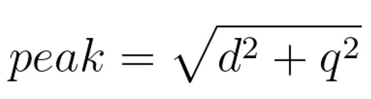
- peak (out)
- Peak value of the dq transformation system. It is given by the following
equation:
- Supported types: real.
- Vector support: no.
- This output is dynamically created when property enable peak measurement [sqrt(d2+q2)] is set to True
- Peak value of the dq transformation system. It is given by the following
equation:
Properties
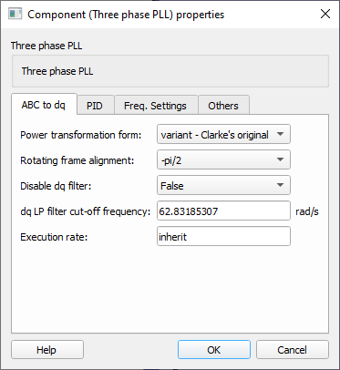
- Power transformation form
- Choose between the methods to perform the transformation. The methods available are:
- Variant – Clarke's original: Use this method when you want the resulting dq0 rotating frame to be amplitude invariant. That is, the amplitude of the original three-phase system will be preserved in the dq0 rotating frame.
- Variant – uniform: Use this method when the input ‘abc frame’ signal is a balanced system and you want the resulting dq0 rotating frame to be amplitude invariant. That is, the amplitude of the original three-phase system will be preserved in the dq0 rotating frame.
- Invariant: Use this method when you want the resulting dq0 rotating frame to be power invariant. That is, the power of the original three-phase system will be preserved in the dq0 rotating frame.
- Choose between the methods to perform the transformation. The methods available are:
- Rotating frame alignment
- Chose to define the alignment of the dq signals (-π/2 = “q”, 0 = “d”).
- Disable dq filter
- Chose to enable or disable a low passive filter on the signals d and q.
- dq LP filter cut-off frequency
- Type in the cutoff frequency of the dq filter in rad/s. This parameter only is available when the property “Disable dq filter” is set to False.
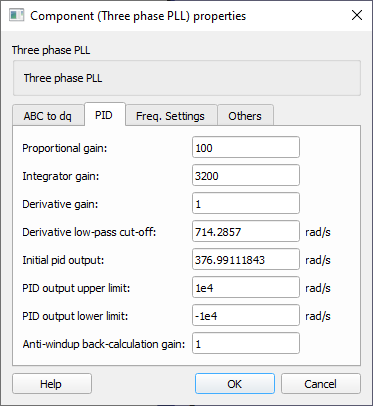
- Proportional gain
- Type in the gain value to be applied to the proportional gain of the PID control block.
- Integrator gain
- Type in the gain value to be applied to the integrator gain of the PID control block.
- Derivative gain
- Type in the gain value to be applied to the differentiator gain of the PID control block.
- Derivative low-pass cut-off
-
Type in the derivative low-pass filter time constant that is used to implement the derivative action since it is not possible to implement a transfer function like Kd . s. The implementation of a derivative action, therefore, is done as in:
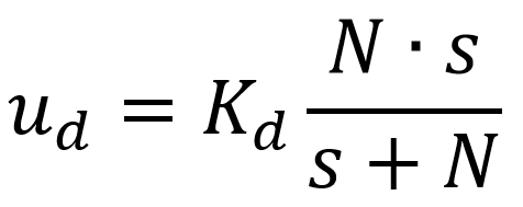
Hence, if N is sufficiently large, ud tends to the ideal implementation of a derivative action Kd . s.
-
- Initial pid output
- Type in the initial condition of PID control action.
- PID output upper limit
- Type in the upper limit of the output signal of the PID block.
- PID output lower limit
- Type in the lower limit of the output signal of the PID block.
- Anti-windup back calculation gain
- Type in the value of the gain of the anti-windup action of the integral parcel of PID controller.
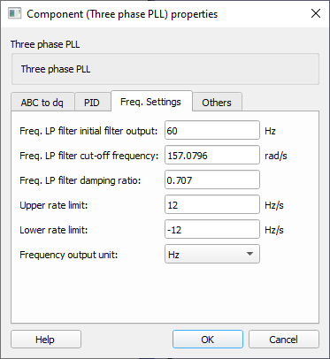
- Freq. LP filter initial filter output
- Type in the initial value of the low-pass filter for the output frequency.
- Freq. LP filter cut-off frequency
- Type in the cutoff frequency of the low-pass filter for the output frequency.
- Freq. LP filter damping ratio
- Type in the damping ratio of the second-order low-pass filter for the output frequency.
- Upper rate limit
- Type in the upper rate limit for the frequency signal that is output by the PID controller and is the input of the second-order low-pass filter.
- Lower rate limit
- Type in the lower rate limit for the frequency signal that is output by the PID controller and is the input of the second-order low-pass filter.
- Frequency output unit
- Choose which frequency unit will be output by the component: Hz or Rad/s.
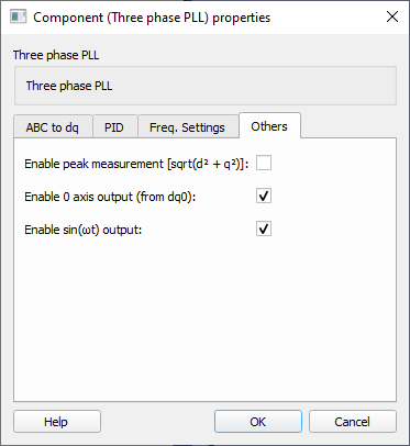
- Enable peak measurement [sqrt(d2+q2)]
- Select it to create an output for the component which will output the peak measurement of the three-phase input signal.
- Enable 0 axis output (from dq0)
- Select it to create an output for the component which will output the zero component of the abc-frame input.
- Enable sin(ωt) output
- Select it to create an output for the component which will output the value of the trigonometric function ‘sin’ applied to the value of the phase of the three-phase system.
- Execution rate
- Type in the desired signal processing execution rate. This value must be compatible with other signal processing components of the same circuit: the value must be a multiple of the fastest execution rate in the circuit. There can be up to four different execution rates. To specify the execution rate, you can use either decimal (e.g. 0.001) or exponential values (e.g. 1e-3) in seconds. Alternatively, you can type in ‘inherit’ in which case the component will be assigned execution rate based on the execution rate of the components it is receiving input from.