Single Phase PLL
Description of the Single Phase PLL component in Schematic Editor, which generates an output signal whose phase is related to the phase of an input signal.
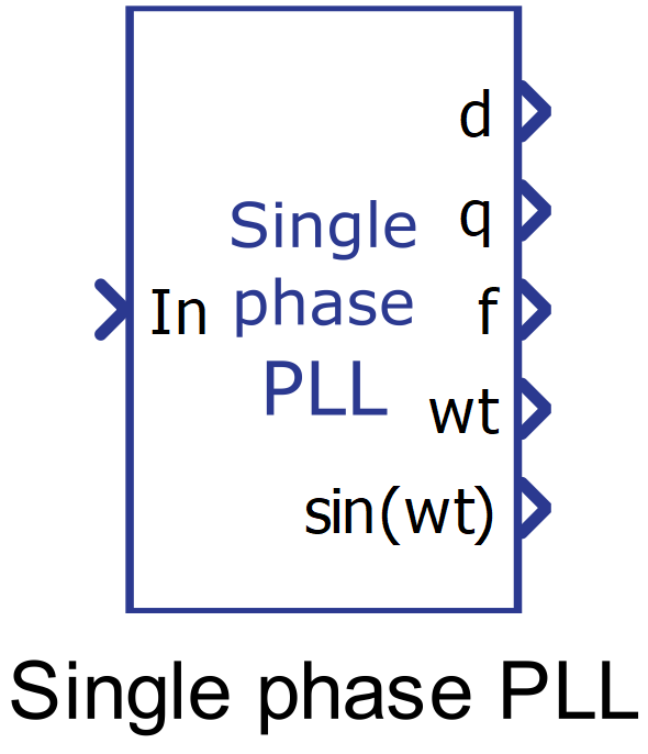
Component Icon
Description
The single phase PLL component has two operation modes, with enabled gain scheduling where P, I and D gains depend on error and will vary between lower and higher values. If the scheduling is disabled lower values of P, I and D gains will be used.
Single phase PLL component is based on Second Order Generalized integrator (SOGI). The second order generalized integrator has been widely used to implement grid synchronization for grid-connected converters.
A conceptual block diagram of the synchronous frame single phase PLL is shown in Figure 2.

The sinusoidal input value is represented by vi. K is the damping factor of the SOGI algorithm. The αβ signals, generated by SOGI algorithm are transformed into direct-quadrature frame through the Park transformation.
The q-axis part of the signal in the dq reference frame, normalized with amplitude as the base value, represents the error signal which feeds the PID block. The goal of the PID is to keep q-axis part on the zero value, which captures whole input signal in d-axis. Thus, d-axis value represents value synchronized with the input signal.
Ports
- In (in)
- Sinusoidal input of the single-phase system whose phase and frequency is intended to
be extracted.
- Supported types: real.
- Vector support: no.
- Sinusoidal input of the single-phase system whose phase and frequency is intended to
be extracted.
- d (out)
- Output signal of the component related to the direct component of the αβ-frame
input.
- Supported types: real.
- Vector support: no.
- Output signal of the component related to the direct component of the αβ-frame
input.
- q (out)
- Output signal of the component related to the quadrature component of the αβ -frame
input.
- Supported types: real.
- Vector support: no.
- Output signal of the component related to the quadrature component of the αβ -frame
input.
- f (out)
- Frequency (Hz) of the single-phase input system.
- Supported types: real.
- Vector support: no.
- Frequency (Hz) of the single-phase input system.
- wt (out)
- Angle of the single-phase input system.
- Supported types: real.
- Vector support: no.
- Angle of the single-phase input system.
- sin(wt) (out)
- Value of the trigonometric function ‘sin’ applied to the value of the phase of the
single-phase system.
- Supported types: real.
- Vector support: no.
- Value of the trigonometric function ‘sin’ applied to the value of the phase of the
single-phase system.
Properties
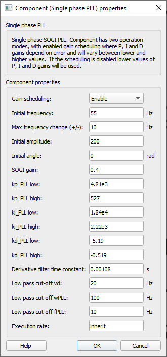
- Gain scheduling
- Select for allowing for variable PID gains whose values depend on error amplitude. If this property is set to “Disable”, the gains of the PID controller will assume the lower values that are set on the component.
- Initial frequency
- Type in the initial frequency of the calculated PLL output signal.
- Max frequency change (+/-)
- Type in the maximum range around the initial frequency that the input signal is allowed to vary.
- Initial amplitude
- Type in the initial amplitude of the calculated PLL output signal.
- Initial angle
- Type in the initial angle of the calculated PLL output signal.
- SOGI gain
- Type in the dumping factor to be applied to the SOGI algorithm.
- kp_PLL low
- Type in the lowest gain value to be applied to the proportional gain of the PID control block.
- kp_PLL high
- Type in the highest gain value to be applied to the proportional gain of the PID control block.
- ki_PLL low
- Type in the the lowest gain value to be applied to the integral gain of the PID control block.
- ki_PLL high
- Type in the the highest gain value to be applied to the integral gain of the PID control block.
- kd_PLL low
- Type in the the lowest gain value to be applied to the derivative gain of the PID control block.
- kd_PLL high
- Type in the highest gain value to be applied to the derivative gain of the PID control block.
- Derivative filter time constant
-
Type in the derivative low-pass filter time constant that is used to implement the derivative action since it is not possible to implement a transfer function like Kd . s. The implementation of a derivative action, therefore, is done as in:
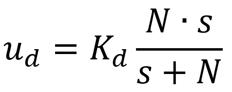
Hence, if N is sufficiently large, ud tends to the ideal implementation of a derivative action Kd . s.
-
- Low-pass cut-off vd
- Type in the cut-off frequency of the low-pass filter applied to the direct component of the dq-frame input.
- Low-pass cut-off wPLL
- Type in the cut-off frequency of the low-pass filter applied to the internal angular frequency used to calculate the virtual β signal of the αβ-frame.
- Low-pass cut-off fPLL
- Type in the cut-off frequency of the low-pass filter applied to the frequency output by the component.
- Execution rate
- Type in the desired signal processing execution rate. This value must be compatible with other signal processing components of the same circuit: the value must be a multiple of the fastest execution rate in the circuit. There can be up to four different execution rates. To specify the execution rate, you can use either decimal (e.g. 0.001) or exponential values (e.g. 1e-3) in seconds. Alternatively, you can type in ‘inherit’ in which case the component will be assigned execution rate based on the execution rate of the components it is receiving input from.