ABC to DQ
Description of the ABC to DQ component in Schematic Editor, which performs an ABC to dq transformation
Description
This component performs the ABC to DQ0 transformation, which is a cascaded combination of Clarke's and Park's transformations. This transformation projects directly the three-phase quantities into a synchronously rotating frame. This component has the same three modes as the ABC to αβ transformation and the same two alignment modes as the αβ to dq transformation. See ABC to Alpha Beta and Alpha Beta to DQ for more details.
The component itself is composite and it is composed of ABC to αβ and αβ to DQ as in Figure 2.
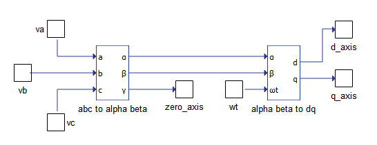
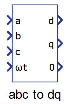
The inputs to this component are the three-phase quantities and the angle ωt. The outputs are the signals d, q, and 0, where 0 is equal to the γ signal from the ABC to αβγ transformation.
The parameter Power transformation form allows the selection of the power transformation mode, while the parameter Rotating frame alignment allows the selection of the alignment mode.
The parameter Disable dq filter allows the disabling of a low passive filter on the signals d and q. The filters are disabled by default. By enabling the filter, the properties window changes, allowing the definition of the cutoff angular frequency and the filter's initial output through the parameters dq filter cutoff frequency and Initial dq filter output.
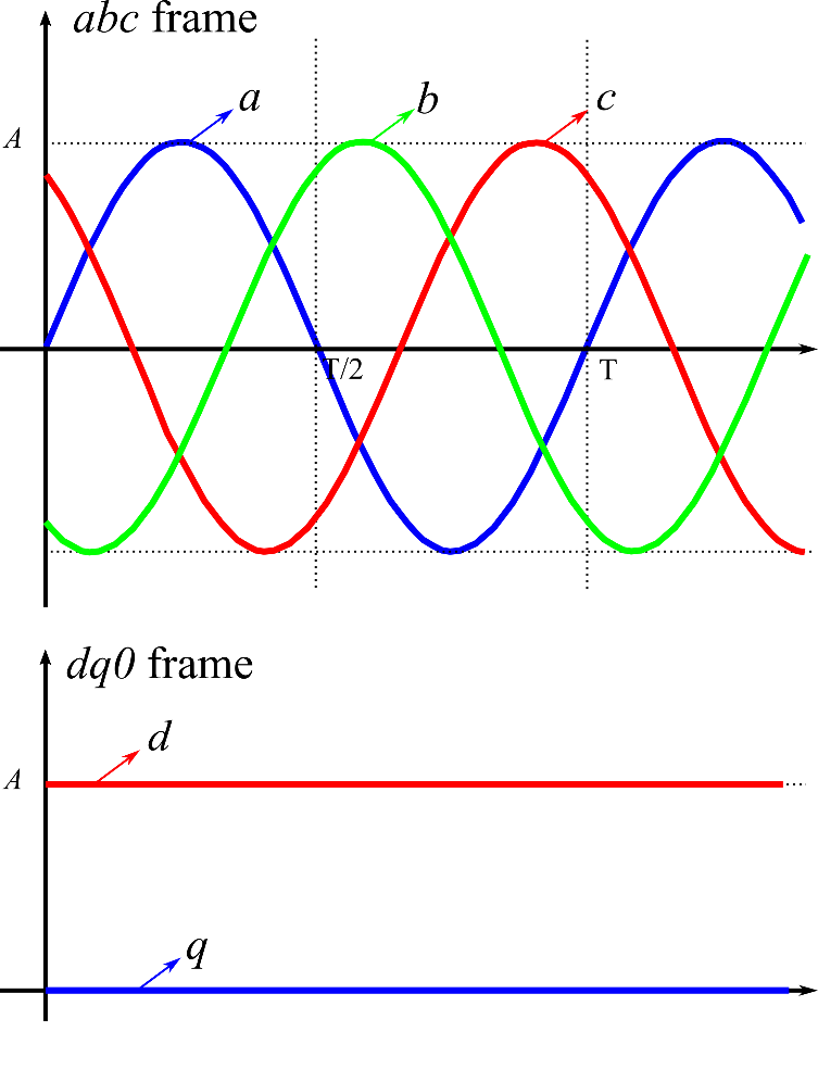
Figure 3 illustrates the transformation of a three-phase system to DQ0 frame.
Ports
- a (in)
- Input a of the component, corresponding to the three-phase abc
system.
- Supported types: uint, int and real.
- Vector support: no.
- Input a of the component, corresponding to the three-phase abc
system.
- b (in)
- Input b of the component, corresponding to the three-phase abc
system.
- Supported types: uint, int and real.
- Vector support: no.
- Input b of the component, corresponding to the three-phase abc
system.
- c (in)
- Input c of the component, corresponding to the three-phase abc
system.
- Supported types: uint, int and real.
- Vector support: no.
- Input c of the component, corresponding to the three-phase abc
system.
- ωt (in)
- Angular position of the dq rotating frame, in radians (0-2π).
- Supported types: uint, int and real.
- Vector support: no.
- Angular position of the dq rotating frame, in radians (0-2π).
- d (out)
- Output signal of the component related to the direct component of the
input abc frame.
- Supported types: real.
- Vector support: no.
- Output signal of the component related to the direct component of the
input abc frame.
- q (out)
- Output signal of the component related to the quadrature component of
the input abc frame.
- Supported types: real.
- Vector support: no.
- Output signal of the component related to the quadrature component of
the input abc frame.
- 0 (out)
- Output signal of the component related to the zero component of the
input abc frame.
- Supported types: uint, int and real.
- Vector support: no.
- Output signal of the component related to the zero component of the
input abc frame.
Properties
- Power transformation form
-
Allows choosing between the methods to perform the transformation. The methods available are:
-
Variant – Clarke's original: Use this method when you want the resulting dq0 rotating frame to be amplitude invariant. That is, the amplitude of the original three-phase system will be preserved in the dq0 rotating frame.
-
Variant – uniform: Use this method when the input ‘abc frame’ signal is a balanced system and you want the resulting dq0 rotating frame to be amplitude invariant. That is, the amplitude of the original three-phase system will be preserved in the dq0 rotating frame.
-
Invariant: Use this method when you want the resulting dq0 rotating frame to be power invariant. That is, the power of the original three-phase system will be preserved in the dq0 rotating frame.
-
-
- Rotating frame alignment
- Defines the alignment of the dq signals (-π/2 = “q”, 0 = “d”).
- Disable dq filter
- Allows the disabling of a low passive filter on signals d and q.
- Initial dq filter output
- Available only if the property Disable dq filter is set to False.
- Specifies the initial value of the filter’s output.
- dq filter cutoff frequency
- Available only if the property Disable dq filter is set to False.
- Specifies the cutoff frequency of the dq filter in rad/s.
- Execution rate
- Type in the desired signal processing execution rate. This value must be compatible with other signal processing components of the same circuit: the value must be a multiple of the fastest execution rate in the circuit. There can be up to four different execution rates. To specify the execution rate, you can use either decimal (e.g. 0.001) or exponential values (e.g. 1e-3) in seconds. Alternatively, you can type in ‘inherit’ in which case the component will be assigned execution rate based on the execution rate of the components it is receiving input from.
- Tunable
- Available only if property Disable dq filter is set to False.
 Tunable is ignored in
TyphoonSim and changing its value will not affect TyphoonSim
simulation at all.
Tunable is ignored in
TyphoonSim and changing its value will not affect TyphoonSim
simulation at all.- Enables run-time tuning of the selected component. This will allow you to change values for dq filter cutoff frequency during simulation without the need to recompile the model. Tunable properties are available in HIL SCADA in Model Explorer.