Power Measurements
Summary of the Power Measurements components available in Schematic Editor.
This sub-category provides several Power measurement components. Their descriptions and supported features are given in Table 1.
| Component | Description | Features | Help file | ||
|---|---|---|---|---|---|
| Supported input types | Supported output types | Vector support | |||
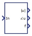
Harmonic Analyzer |
Calculates amplitude, phase, and frequency of the chosen harmonics. Outputs are scalars if the Hamonic order value is scalar, while if the Hamonic order value is a Python list, outputs will be vectors. The component consists of two parts, with one part working on a faster execution rate than the other. The slower part is used to calculate FFT. | real | real | no | Harmonic Analyzer |

Phase Difference |
Calculates phase difference between the input signals. | real | real | no | Phase Difference |
Positive, Negative and Zero Power Meter |
Calculates the positive, negative, and zero power sequence for input signals. For successful operation of the component block, 1/(frequency*execution rate) must be an integer greater than 4. |
real | real | no | Positive Negative Zero Power |

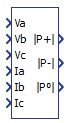
Power Meter |
Computes active and reactive power (both instantaneous and average), apparent power, and power factor for three phase systems. | real | real | no | Power Meter |

Single Phase Phasor |
Calculates phasor (magnitude and angle) of the input signal. | real | real | no | Single Phase Phasor |

Single Phase Power Meter |
Computes active and reactive power for single phase systems. Inputs are the instant voltage and current. | real | real | no | Single Phase Power Meter |
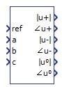
Symmetrical Components |
Gives phasors of symmetrical components of the input signals. For successful operation of the component block, 1/(frequency*execution rate) must be an integer greater than 4. |
real | real | no | Symmetrical Components |
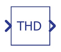 THD Measurement |
Calculates total harmonic distortion of the observed signal, based on the THD+N
approach. The component consists of two components; the first one is buffer which has to work on a faster execution rate, and the second one has to work on a much slower execution rate. The component with a slower execution rate is used for FFT calculation and other needed arithmetic. |
real | real | no | THD (Total Harmonic Distortion) Measurement |

Three Phase Phasor |
Calculates phasors (magnitude and angle) of the input signals. | real | real | no | Three Phase Phasor |