Three Phase Phasor
Description of the Three Phase Phasor component in Schematic Editor, which returns the amplitudes and phases of a three-phase input signal.
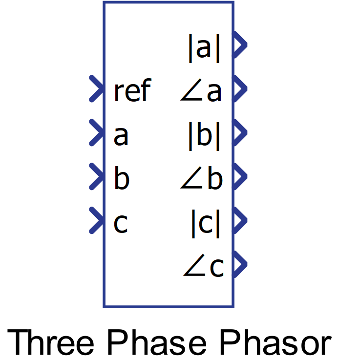
Component Icon
Description
The three phase phasor component returns the amplitudes and phases of a three-phase input signal.
The phase of the signal is calculated by comparing the input signal with the reference signal.
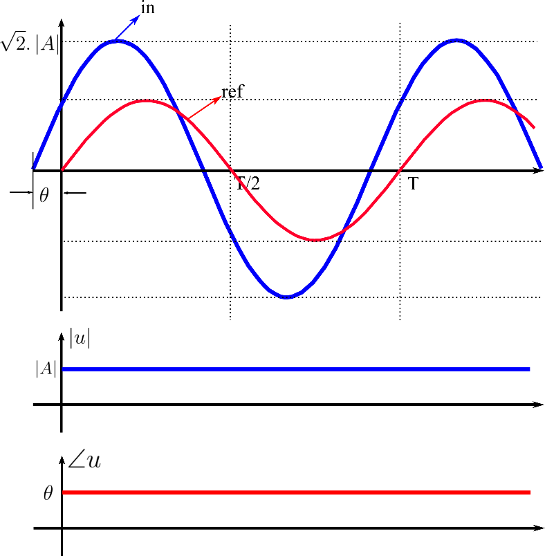
Figure 2 shows how the three-phase phasor component work. In the example, for the input signal ‘a’ illustrated in the upper waveforms, the reference signal is plotted as a red sinusoidal waveform and the input signal is plotted as a blue sinusoidal waveform with a phase shift (theta) in comparison with the reference signal and an amplitude A.
In the bottom waveforms, the measured amplitude of the input signal A is plotted in blue and the phase (theta) between reference and input signals is plotted in red and its unit is degrees.
For the input signals ‘b’ and ‘c’, the behavior of the component is reproduced as in the example for input ‘a’.
Ports
- Ref (in)
- Reference signal for the angle measurement.
- Supported types: real.
- Vector support: no.
- Reference signal for the angle measurement.
- a (in)
- Input signal ‘a’ whose amplitude and phase are measured.
- Supported types: real.
- Vector support: no.
- Input signal ‘a’ whose amplitude and phase are measured.
- b (in)
- Input signal ‘b’ whose amplitude and phase are measured.
- Supported types: real.
- Vector support: no.
- Input signal ‘b’ whose amplitude and phase are measured.
- c (in)
- Input signal ‘c’ whose amplitude and phase are measured.
- Supported types: real.
- Vector support: no.
- Input signal ‘c’ whose amplitude and phase are measured.
- |a| (out)
- Amplitude value of phasor a.
- Supported types: real.
- Vector support: no.
- Amplitude value of phasor a.
- <a (out)
- Value of the phase difference, in degrees, between input signal ‘a’ and ‘ref’.
- Supported types: real.
- Vector support: no.
- Value of the phase difference, in degrees, between input signal ‘a’ and ‘ref’.
- |b| (out)
- Amplitude value of phasor b.
- Supported types: real.
- Vector support: no.
- Amplitude value of phasor b.
- <b (out)
- Value of the phase difference, in degrees, between input signal ‘b’ and ‘ref’.
- Supported types: real.
- Vector support: no.
- Value of the phase difference, in degrees, between input signal ‘b’ and ‘ref’.
- |c| (out)
- Amplitude value of phasor c.
- Supported types: real.
- Vector support: no.
- Amplitude value of phasor c.
- <c (out)
- Value of the phase difference, in degrees, between input signal ‘c’ and ‘ref’.
- Supported types: real.
- Vector support: no.
- Value of the phase difference, in degrees, between input signal ‘c’ and ‘ref’.
Properties
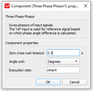
- Zero cross wait timeout
- Type in the period used as base to calculate the zero crossing of input signals. If the frequency of the input signal is small enough such that the timeout period is bigger than the input signal period, the phase of the input signals is not correctly measured.
- Angle unit
- Angle can be expressed in radians or degrees.
- Execution rate
- Type in the desired signal processing execution rate. This value must be compatible with other signal processing components of the same circuit: the value must be a multiple of the fastest execution rate in the circuit. There can be up to four different execution rates. To specify the execution rate, you can use either decimal (e.g. 0.001) or exponential values (e.g. 1e-3) in seconds. Alternatively, you can type in ‘inherit’ in which case the component will be assigned execution rate based on the execution rate of the components it is receiving input from.