THD (Total Harmonic Distortion) Measurement
Description of the THD Measurement component in Schematic Editor, which calculates the total harmonic distortion of the input signal.
Component Icon

Description
THD measurement block calculates total harmonic distortion of the input signal.
Fundamental harmonic frequency of the input is specified by user through Fundamental frequency property. It should be noted that the results will be more precise if the period of the signal is divisible by the execution rate value (the ratio is an integer number).
- The input signal is sampled during the time of solver execution step
- RMS value of the signal and its fundamental harmonic are calculated. Value of the
fundamental harmonic RMS is obtained using discrete Fourier transformation. Real and
imaginary part of the fundamental harmonic are calculated first:
RMS value of the fundamental harmonic is calculated afterwards:
where N represents number of samples and it is calculated as ratio between period of the signal and the execution rate.
Division by is performed in order to derive the RMS value from the amplitude.
- Output value of THD is calculated by the following equation:
,
where Arms represents the rms value of the input signal.
Ports
- In (in)
- Signal for which to calculate the THD value.
- Supported types: real.
- Vector support: no.
- Signal for which to calculate the THD value.
- Out (out)
- Calculated THD value.
- Supported types: real.
- Vector support: no.
- Calculated THD value.
Properties
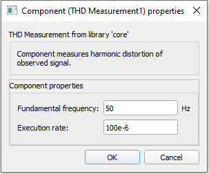
- Fundamental frequency
- Type in the fundamental harmonic frequency of the input signal.
- Execution rate
- Type in the desired signal processing execution rate. This value must be compatible with other signal processing components of the same circuit: the value must be a multiple of the fastest execution rate in the circuit. There can be up to four different execution rates. To specify the execution rate, you can use either decimal (e.g. 0.001) or exponential values (e.g. 1e-3) in seconds. Alternatively, you can type in ‘inherit’ in which case the component will be assigned execution rate based on the execution rate of the components it is receiving input from.