Positive Negative Zero Power
Description of the Positive Negative Zero Power component in Schematic Editor, which calculates the power of symmetrical component sequences.
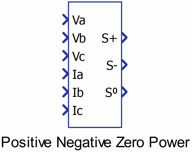
Component Icon
Description
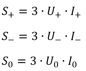
Calculates the power of symmetrical component sequences.
The component takes phase voltages and currents of the three-phase circuit and outputs the powers of positive, negative and zero sequences of that circuit.
Input voltages and currents are transformed from time to complex domain first. After that, the positive negative and zero sequence phasors are calculated for both sets of values by using symmetrical components transformation:
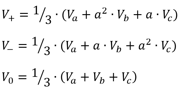
where a represents rotating phasor: ![]()
To ensure the correct output of the component, it is necessary to ensure that the
![]()
Ports
- Va (in)
-
Input ‘Va’ of the component, corresponding to the voltage of three-phase abc system.
- Supported types: uint, int and real.
- Vector support: no.
-
- Vb (in)
- Input ‘Vb’ of the component, corresponding to the voltage of three-phase abc
system.
- Supported types: uint, int and real.
- Vector support: no.
- Input ‘Vb’ of the component, corresponding to the voltage of three-phase abc
system.
- Vc (in)
- Input ‘Vc’ of the component, corresponding to the voltage of three-phase abc
system.
- Supported types: uint, int and real.
- Vector support: no.
- Input ‘Vc’ of the component, corresponding to the voltage of three-phase abc
system.
- Ia (in)
-
Input ‘Ia’ of the component, corresponding to the current of three-phase abc system.
- Supported types: uint, int and real.
- Vector support: no.
-
- Ib (in)
-
Input ‘Ib’ of the component, corresponding to the current of three-phase abc system.
- Supported types: uint, int and real.
- Vector support: no.
-
- Ic (in)
-
Input ‘Ic’ of the component, corresponding to the current of three-phase abc system.
- Supported types: uint, int and real.
- Vector support: no.
-
- S+ (out)
- Apparent power of the positive sequence.
- Supported types: real.
- Vector support: no.
- Apparent power of the positive sequence.
- S- (out)
- Apparent power of the negative sequence.
- Supported types: real.
- Vector support: no.
- Apparent power of the negative sequence.
- S0 (out)
- Apparent power of the zero sequence.
- Supported types: real.
- Vector support: no.
- Apparent power of the zero sequence.
Properties
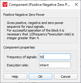
- Frequency of the signals
- Type in the input signals frequency using this property. The component calculates the output using fixed frequency value.
- Execution rate
- Type in the desired signal processing execution rate. This value must be compatible with other signal processing components of the same circuit: the value must be a multiple of the fastest execution rate in the circuit. There can be up to four different execution rates. To specify the execution rate, you can use either decimal (e.g. 0.001) or exponential values (e.g. 1e-3) in seconds. Alternatively, you can type in ‘inherit’ in which case the component will be assigned execution rate based on the execution rate of the components it is receiving input from.