Power Meter
Description of the Power Meter component in Schematic Editor, which computes active and reactive power (both instantaneous and average), apparent power, and power factor for three phase systems.
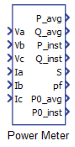
Component Icon
Description
The Power Meter component is based on instantaneous power theory. Conventional power theory uses voltage and current rms values to compute power values, which makes it valid only for steady state analysis. Instantaneous power theory, on the other hand, utilizes instantaneous voltage and current values to compute instantaneous real, reactive, and zero power. Consequently, this theory is useful for both transient and steady-state analysis, which is more suitable for power electronics applications.
- P_avg – average active power; calculated as the average value of instantaneous real power; in steady states, this quantity is equivalent to the active power computed by conventional power theory.
- Q_avg – average reactive power; calculated as the average value of instantaneous reactive power; in steady states, this quantity is equivalent to conventional theory reactive power.
- P_inst – instantaneous real power; compared with symmetrical component theory, this power represents the instantaneous value of the direct and inverse sequence powers combined.
- Q_inst – instantaneous reactive power; it represents the power that is being exchanged by the phases of the system. It does not contribute to the energy transfer between the observed three phase nodes at any time.
- S – apparent power; calculated based on average active and average reactive power. This is also quantity that is equivalent to appropriate conventional theory definition in steady states.
- pf – power factor; ratio between average active power and apparent power. It is another quantity equivalent to conventional theory definition during steady states.
- P0_avg – average value of zero sequence power;
- P0_inst – instantaneous value of zero sequence power.
- a constant part, which represents the average value of zero power (measured by P0_avg port);
- an oscillating part, which oscillates at an amplitude equal to the constant part and with a frequency two times higher than the voltage and current frequency.
The P0_inst part measures the sum of both zero sequence components.
Finally, it is worth highlighting that the total instantaneous power flow is actually the sum of the instantaneous real and instantaneous zero power, while instantaneous reactive power does not contribute to energy transfer through the system at all.
Average power values P_avg, Q_avg, and P0_avg are calculated afterwards by averaging P_inst, Q_inst, and P0_inst, respectively. They are computed through the implementation of a first-order or second-order (user selectable) low-pass filter.
Ports
- Va (in)
- Signal related to the measured voltage of the phase ‘a’ of the three-phase power
system.
- Supported types: real.
- Vector support: no.
- Signal related to the measured voltage of the phase ‘a’ of the three-phase power
system.
- Vb (in)
- Signal related to the measured voltage of the phase ‘b’ of the three-phase power
system.
- Supported types: real.
- Vector support: no.
- Signal related to the measured voltage of the phase ‘b’ of the three-phase power
system.
- Vc (in)
- Signal related to the measured voltage of the phase ‘c’ of the three-phase power
system.
- Supported types: real.
- Vector support: no.
- Signal related to the measured voltage of the phase ‘c’ of the three-phase power
system.
- Ia (in)
- Signal related to the measured current of the phase ‘a’ of the three-phase power
system.
- Supported types: real.
- Vector support: no.
- Signal related to the measured current of the phase ‘a’ of the three-phase power
system.
- Ib (in)
- Signal related to the measured current of the phase ‘b’ of the three-phase power
system.
- Supported types: real.
- Vector support: no.
- Signal related to the measured current of the phase ‘b’ of the three-phase power
system.
- Ic (in)
- Signal related to the measured current of the phase ‘c’ of the three-phase power
system.
- Supported types: real.
- Vector support: no.
- Signal related to the measured current of the phase ‘c’ of the three-phase power
system.
- P_avg (out)
- Calculated value of the average active power of the three-phase power system.
- Supported types: real.
- Vector support: no.
- Calculated value of the average active power of the three-phase power system.
- Q_avg (out)
- Calculated value of the average reactive power of the three-phase power system.
- Supported types: real.
- Vector support: no.
- Calculated value of the average reactive power of the three-phase power system.
- P_inst (out)
- Calculated value of the instantaneous real power of the three-phase power system.
- Supported types: real.
- Vector support: no.
- This port is dynamically created when the property Enable instantaneous power measurement ports is enabled
- Calculated value of the instantaneous real power of the three-phase power system.
- Q_inst (out)
- Calculated value of the instantaneous reactive power of the three-phase power
system.
- Supported types: real.
- Vector support: no.
- This port is dynamically created when the property Enable instantaneous power measurement ports is enabled
- Calculated value of the instantaneous reactive power of the three-phase power
system.
- S (out)
- Calculated value of the instantaneous apparent power of the three-phase power
system.
- Supported types: real.
- Vector support: no.
- Calculated value of the instantaneous apparent power of the three-phase power
system.
- pf (out)
- Calculated value of the system's power factor.
- Supported types: real.
- Vector support: no.
- Calculated value of the system's power factor.
- P0_avg
- Calculated value of the system's average value of zero sequence power.
- Supported types: real.
- Vector support: no.
- This port is dynamically created when the property Enable zero power measurement ports is enabled
- Calculated value of the system's average value of zero sequence power.
- P0_inst
- Calculated value of the system's instantaneous value of zero sequence power..
- Supported types: real.
- Vector support: no.
- This port is dynamically created when the property Enable zero power measurement ports is enabled
- Calculated value of the system's instantaneous value of zero sequence power..
Properties
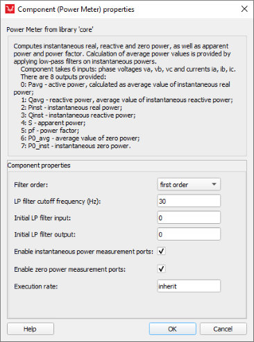
- Filter order
- Choose the order of the built-in low-pass filter of the component. Available options are: No filter, first order, and second order.
- LP filter cutoff frequency (Hz)
- Type in the cutoff frequency of the built-in low-pass filter.
- Initial LP filter input
- Type in the initial value of the input of the low-pass filter.
- Initial LP filter output
- Type in the initial value of the output of the low-pass filter.
- Enable instantaneous power measurement ports
- Select to enable/disable P_inst and Q_inst ports.
- Instantaneous power measurements are enabled by default.
- Select to enable/disable P_inst and Q_inst ports.
- Enable zero power measurement ports
- Select to enable/disable P0_inst and Q0_inst measurement ports.
- Zero power measurements are disabled by default, for backward compatibility reasons.
- Select to enable/disable P0_inst and Q0_inst measurement ports.
- Execution rate
- Type in the desired signal processing execution rate. This value must be compatible with other signal processing components of the same circuit: the value must be a multiple of the fastest execution rate in the circuit. There can be up to four different execution rates. To specify the execution rate, you can use either decimal (e.g. 0.001) or exponential values (e.g. 1e-3) in seconds. Alternatively, you can type in ‘inherit’ in which case the component will be assigned execution rate based on the execution rate of the components it is receiving input from.