System
Summary of the System signal processing components available in Schematic Editor.
This sub-category provides thirteen System components. Their descriptions and supported features are given in Table 1.
| Component | Description | Features | Help file | ||
|---|---|---|---|---|---|
| Supported input types | Supported output types | Vector support | |||
|
Boolean Join |
Joins elements of the input vector into a single or multiple uint signals using weighted binary code. Input vector elements are considered as Boolean values. Output signal is vector for input vectors larger than 32 | real, int, uint | uint | yes | Boolean Join |
|
Boolean Split |
Splits weighted binary coded uint input signal into a vector of Boolean valued signals. Output vector size is defined in the component properties, and it must be less than or equal to the input vector size times 32. | uint | real, int, uint | yes | Boolean Split |

Bus Join |
Concatenates input signals (scalar or vector) into a bus. | real, int, uint | real, int, uint | yes | Bus Join |
 Bus Modify |
Changes one (or more) elements in the input vector and outputs a modified vector signal. |
real, int, uint | real, int, uint | yes | Bus Modify |
 Bus Selector |
Selects signals from input vector, by their indexes, and outputs them as scalars or vectors. |
real, int, uint | real, int, uint | yes | Bus Selector |

Bus Split |
Splits vector input signal into scalar or specified vector outputs. |
real, int, uint | real, int, uint | yes | Bus Split |
 CPU Time Slot Utilization |
Displays the time slot utilization of the selected CPU core with full resolution | - | real, int, uint | no | CPU Time Slot utilization |

Data Type Conversion |
Converts input signal data type. | real, int, uint | real, int, uint, (user selectable) | yes | Data Type Conversion |
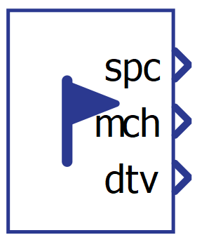 HIL Flags Status |
Outputs the SPC Arithmetic Overflow, Machine Arithmetic Overflow, and Dead Time Violation flag statuses of the selected HIL device. | - | real, int, uint | no | HIL Flags Status |

Multiport Signal Switch |
Outputs one of multiple input signals based on the control signal value. | real, int, uint | real, int, uint | yes | Multiport Signal Switch |

Rate Transition |
Manages data transfer between components that operate at different execution rates. | real, int, uint | real, int, uint | yes | Rate Transition |

Signal Switch |
Outputs one of two input signals based on the control signal value. | real, int, uint | real, int, uint | yes | Signal Switch |
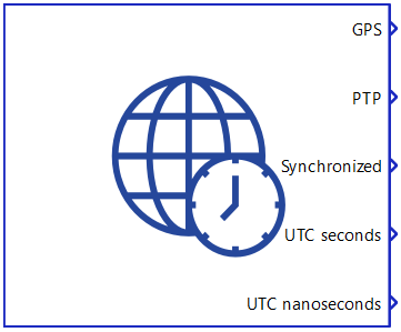
Time Synchronization |
Configures the time synchronization on a HIL device and monitors its status. | - | - | - | Time synchronization |
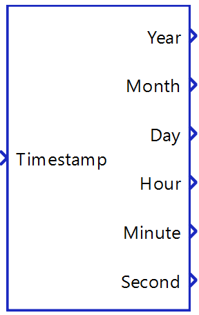 Timestamp to Datetime |
Converts a UTC timestamp into a human-readable format. | uint | uint | no | Timestamp To Datetime |