Multiport Signal Switch
Description of the Multiport Signal Switch component in Schematic Editor, which selects one of several inputs depending on the value of a control signal.
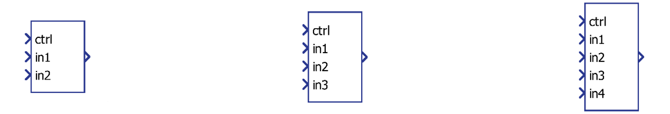
Component Icon
Description
Multiport signal switch component outputs the corresponding input according to the integer value of control signal input.
The functionality of this component is the same as a switch/case statement in the C programing language. The pseudocode can be written as:
switch (ctrl):
    case 1: out = in1
    case 2: out = in2
    case 3: out = in3
    ...
    default: out = 0
The control signal is always converted to an integer value before the switch statement is performed.
All inputs except the control input can be scalars or vectors. The control input must be scalar. If vectors are used, all vectors must be the same length and the output signal will be a vector.
Ports
- Input n (in)
- Input signal n, where n is the number of inputs of the component and is
set in the property Number of inputs terminals.
- Supported types: uint, int and real.
- Vector support: yes.
- In the case of vector input signals, all input signals must be vectors and have the same dimension.
- Input signal n, where n is the number of inputs of the component and is
set in the property Number of inputs terminals.
- Control input (in)
- Integer value corresponding to the index of the input signal that will
be forwarded. The minimum value of this input is “1” and the maximum
value is “n”. Any value out of this range will result in 0 on the
output..
- Supported types: uint, int and real.
- Vector support: no.
- Integer value corresponding to the index of the input signal that will
be forwarded. The minimum value of this input is “1” and the maximum
value is “n”. Any value out of this range will result in 0 on the
output..
- Output (out)
- The output of the component, which is the same as the selected input
signal.
- Supported types: uint, int and real.
- The output type is inherited from the input signal.
- Vector support: yes.
- The vector length is inherited from input signals.
- Supported types: uint, int and real.
- The output of the component, which is the same as the selected input
signal.
Properties
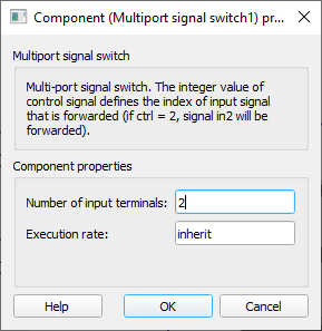
- Number of input Terminals
- Type in the number of inputs that the component will have. This parameter must be an integer.
- Execution rate
- Type in the desired signal processing execution rate. This value must be compatible with other signal processing components of the same circuit: the value must be a multiple of the fastest execution rate in the circuit. There can be up to four different execution rates. To specify the execution rate, you can use either decimal (e.g. 0.001) or exponential values (e.g. 1e-3) in seconds. Alternatively, you can type in ‘inherit’ in which case the component will be assigned execution rate based on the execution rate of the components it is receiving input from.