Signal Switch
Description of the Signal Switch component, which selects one of two inputs depending on the value of a control signal.
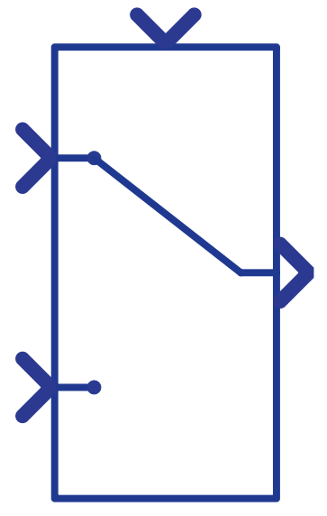
Component Icon
Description
The Signal Switch component outputs input 1 when a control input meets the selected criterion, and outputs input 2 when the control input does not meet the selected criterion.
Selection criteria and threshold can be set using component properties. Criteria can be:
- >= - greater than or equal to
- > - greater than
- != - not equal to
Criteria are always checked for the control signal (signal going to the top of the component). If the criteria are met, signal 1 is passed to the output, otherwise, signal 2 is passed.
Signals can be scalars or vectors. If signals are vectors, they must be of same length and the operation is performed element-wise. If there is a mixture of scalar and vector signals, that scalar value will be used in the element-wise operations. The examples in Table 1 illustrate this.
| Example | in 1 | in 2 | ctrl | criteria | threshold | out |
|---|---|---|---|---|---|---|
| Example 1 | 2 | 3 | 1 | ctrl >= threshold | 10 |
2 if 1 >= 10 else 3 out = 3 |
| Example 2 | 1 | [2, 3, 4] | [5, 7, 9] | ctrl >= threshold | [6, 6, 9] |
out[0] = 1 if 5 >= 6 else 2 out[1] = 1 if 7 >= 6 else 3 out[2] = 1 if 9 >= 9 else 4 out = [2, 1, 1] |
| Example 3 | [1, 2, 3] | [2, 3, 4] | 5 | ctrl >= threshold | 1 |
[1, 2, 3] if 5 >= 1 else [2, 3, 4] out = [1, 2, 3] |
Ports
- Input 1(in)
- Input signal 1.
- Supported types: uint, int and real.
- Vector support: yes.
- Input signal 1.
- Input 2(in)
- Input signal 2.
- Supported types: uint, int and real.
- Vector support: yes.
- Input signal 2.
- Control input (in)
- Value to which the Threshold is compared in order to output the
correct signal.
- Supported types: uint, int and real.
- Vector support: yes.
- Value to which the Threshold is compared in order to output the
correct signal.
- Output (out)
- The output of the component, which is the same as input 1 or input 2,
depending on the result of the comparison between the control
signal and threshold.
- Supported types: uint, int, and real.
- The output type is inherited from the input signals in1 and in2. The control signal is not used to determine the type.
- Vector support: yes.
- The vector length is inherited from input signals.
- Supported types: uint, int, and real.
- The output of the component, which is the same as input 1 or input 2,
depending on the result of the comparison between the control
signal and threshold.
Properties
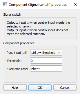
- Pass input 1 if
- Select the logical operation to be performed between control input and threshold. It can be different than (“!=”), greater than or equal to (“>=”), or greater than (“>”).
- Threshold
- Type in the value to which the control input is compared in order to output the correct signal.
- Execution rate
- Type in the desired signal processing execution rate. This value must be compatible with other signal processing components of the same circuit: the value must be a multiple of the fastest execution rate in the circuit. There can be up to four different execution rates. To specify the execution rate, you can use either decimal (e.g. 0.001) or exponential values (e.g. 1e-3) in seconds. Alternatively, you can type in ‘inherit’ in which case the component will be assigned execution rate based on the execution rate of the components it is receiving input from.