CPU Time Slot utilization
Description of the CPU Time Slot utilization in Schematic Editor.
Component Ignored: This component
is ignored in TyphoonSim. Inputs to this component will be discarded and outputs
from the component will be zeroed during TyphoonSim simulation.
Description
This component displays the time slot utilization of the selected CPU core with full resolution and shows how frequently Computing Interval Overrun (CIO) is actually happening.
To connect this component with desired HIL device, use a Signal Device Marker.
Ports
- Output (cpu_utilization)
- Outputs current CPU time slot utilization in range 0 to 1.0.
- Supported types: real.
- Vector support: no.
- Outputs current CPU time slot utilization in range 0 to 1.0.
- Output (max_cpu_utilization)
- Outputs maximum CPU time slot utilization in range 0 to 1.0.
- Supported types: real.
- Vector support: no.
- Outputs maximum CPU time slot utilization in range 0 to 1.0.
Properties
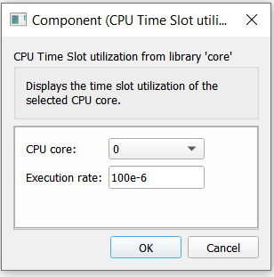
- CPU core
- Defines from which CPU core time slot utilization values will be provided.
- Execution rate
- Type in the desired signal processing execution rate. This value must be compatible with other signal processing components of the same circuit: the value must be a multiple of the fastest execution rate in the circuit. There can be up to four different execution rates. To specify the execution rate, you can use either decimal (e.g. 0.001) or exponential values (e.g. 1e-3) in seconds. Alternatively, you can type in ‘inherit’ in which case the component will be assigned execution rate based on the execution rate of the components it is receiving input from.