Bus Join
Description of the Bus Join component in Schematic Editor, which concatenates input signals into a bus.
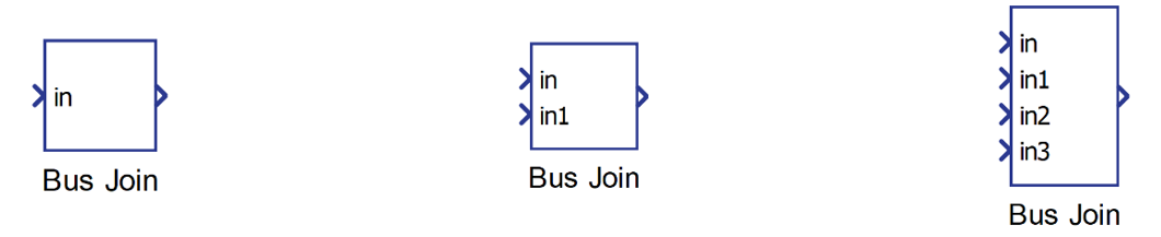
Component Icon
Description
This component concatenates input signals (scalars or vectors) into a bus.
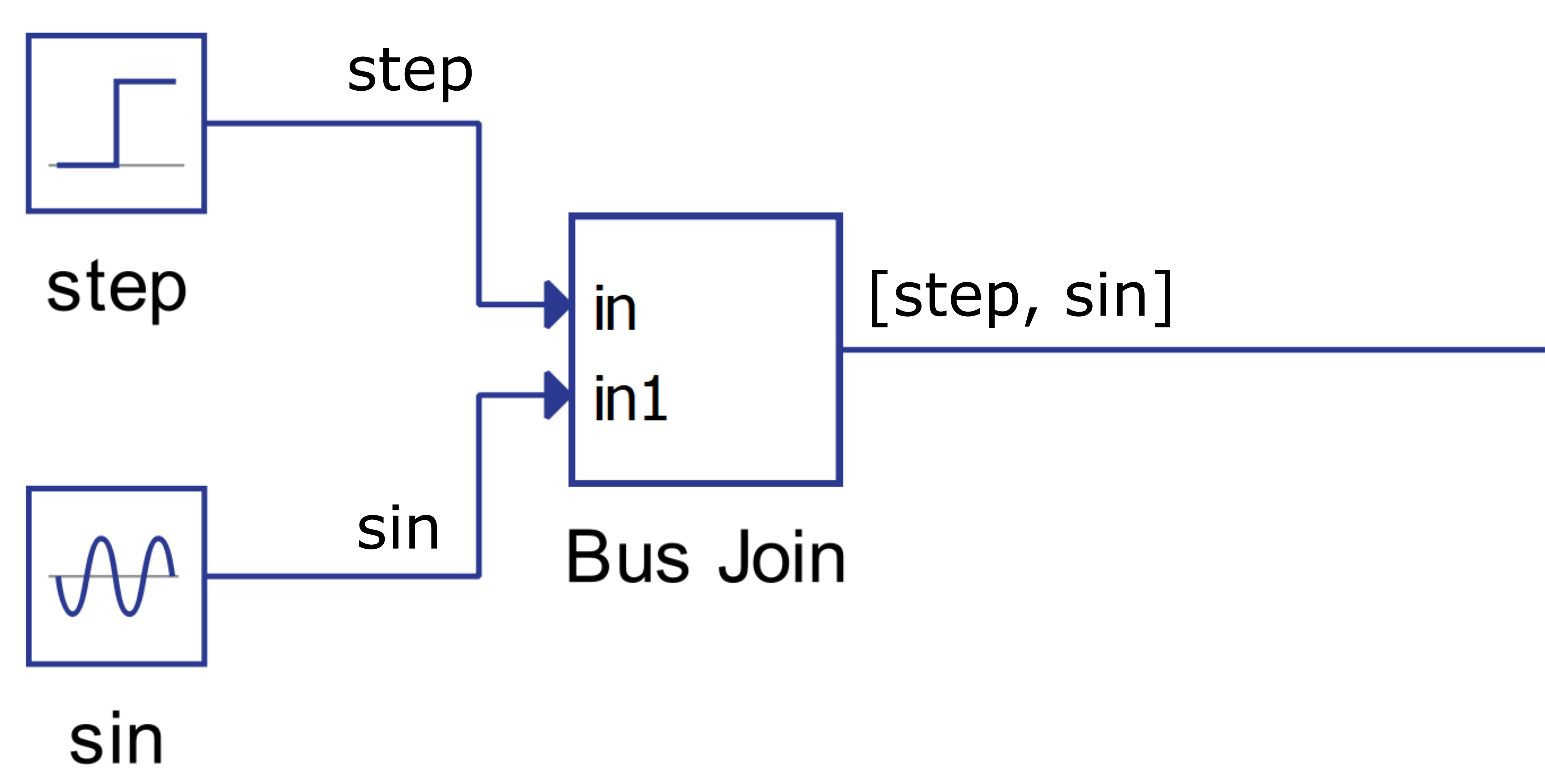
The function of the component is illustrated by an example below. The output signal is a list that contains the two signals connected to its inputs: a step signal and a sinusoidal signal.
The dimension of the output signal will be the sum of the input signal lengths. For example, if input signals are a scalar, vector of 2 and a vector of 3, the output signal will have dimension 6. The signals will be concatenated as they appear on the input. The output signal, for the example, would be [in, in1[0], in1[1], in2[0], in2[1], in2[2]].
Input signals may be of mixed type (real, int or uint).
Ports
- Input (inX)
- Input signal connected to the corresponding terminal of the component.
Depending on the value of the Number of inputs property, a
corresponding number of In terminals is dynamically created.
- Supported types: uint, int and real.
- Vector support: yes
- Input signal connected to the corresponding terminal of the component.
Depending on the value of the Number of inputs property, a
corresponding number of In terminals is dynamically created.
- Output (out)
- The output of the component, which is the concatenation of the inputs of
the component in the form of a vector. The size of the vector is the sum
of all sizes of input signals.
- Supported types: uint, int and real.
- The output type is inherited from the input signal.
- Vector support: yes
- The vector length is defined as the sum of the lengths of input signals.
- Supported types: uint, int and real.
- The output of the component, which is the concatenation of the inputs of
the component in the form of a vector. The size of the vector is the sum
of all sizes of input signals.
Properties
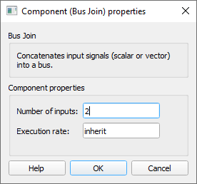
- Number of inputs
- Type in how many inputs the component will concatenate.
- Execution rate
- Type in the desired signal processing execution rate. This value must be compatible with other signal processing components of the same circuit: the value must be a multiple of the fastest execution rate in the circuit. There can be up to four different execution rates. To specify the execution rate, you can use either decimal (e.g. 0.001) or exponential values (e.g. 1e-3) in seconds. Alternatively, you can type in ‘inherit’ in which case the component will be assigned execution rate based on the execution rate of the components it is receiving input from.