CPU Transition
Manages data transfer between components that operate on different CPU cores.

Manages data transfer between components that operate on different CPU cores on the same device. Input and output execution rates may differ.
Note: In TyphoonSim, every part of the model is executed on single PC,
thus CPU Transition will basically behave like Rate Transition component.
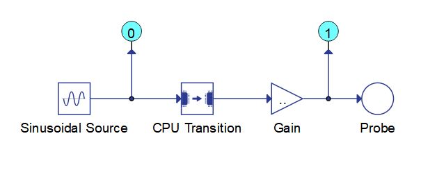
In order for two Signal Processing circuits that run on different User CPUs of the same device to exchange data, they should be connected using the CPU Transition component as illustrated in Figure 2.

CPU Transition component can introduce a delay of one execution rate.
Ports
- Input (in)
- Input signal coming from the source CPU.
- Supported types: uint, int and real.
- Vector support: yes.
- Input signal coming from the source CPU.
- Output (out)
- The output signal present on the destination CPU, with the same value as the input
signal. The execution rate of the signal is defined using the Execution rate
property.
- Supported types: uint, int and real.
- The output type is inherited from the input signal.
- Vector support: yes.
- The vector length is inherited from the input signal.
- Supported types: uint, int and real.
- The output signal present on the destination CPU, with the same value as the input
signal. The execution rate of the signal is defined using the Execution rate
property.
Properties
- init_value
- Initial value of the output signal at the beginning of the simulation.
- Execution rate
- Type in the desired signal processing execution rate. This value must be compatible with other signal processing components of the same circuit: the value must be a multiple of the fastest execution rate in the circuit. There can be up to four different execution rates. To specify the execution rate, you can use either decimal (e.g. 0.001) or exponential values (e.g. 1e-3) in seconds. Alternatively, you can type in ‘inherit’ in which case the component will be assigned execution rate based on the execution rate of the components it is receiving input from.