Bus Split
Description of the Bus Split components in Schematic Editor, which are used to split vectors from its input, convert vectors into scalars, or make vectors on its outputs.
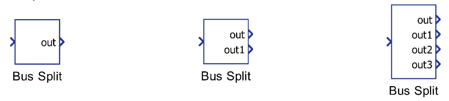
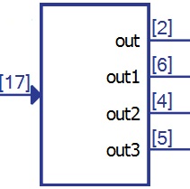
Component Icon
Description
This component splits a vector input signal into scalar or vector outputs.
The Number of outputs property dictates how the input signal will be spit. This property can be an integer or a list.
If you define the value of Number of outputs property with O and the dimension of input signal with I, the rules can be specified as in Table 1.
| O value | Description | Example | |
|---|---|---|---|
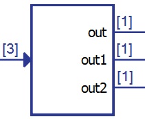
| O is integer | O = I |
Number of outputs is the same as the input signal dimension. The input signal is split into O scalars. |
I = 3, O = 3
|
|
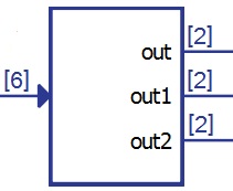
O < I I/O is a round number |
Number of outputs is smaller than input signal dimension and the result of I/O is a round number. Number of output terminals is O and length of each terminal is I/O. |
I = 6, O = 3 I/O = 2
|
|
|
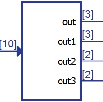
O < I I/O is not a round number |
Number of outputs is smaller than input signal dimension and the result of I/O is not a round number. Number of output terminals is O where first m terminals have dimension I/O+1 and the rest have I/O where m is the reminder of I/O. |
I = 10, O = 4 I/O = 2, m = 2
|
|
|
O > I |
Number of outputs is greater than dimension of input signal. This is an invalid case and it will cause an error. |
||
| O is a list |
sum(O) = I none of elements in O is -1 |
Sum of all elements in the O list is equal to input signal dimension and none of the elements is -1. Number of output terminals is the number of elements in O. Each terminal has dimension as specified in the O list. |
I = 9, O = [1, 5, 3]
|
|
sum(O) = I some elements in O are -1 |
Sum of all elements in the O list is equal to input signal dimension and some elements are -1. The -1 value is for dynamical calculation of dimension. If sum(O) = I, all -1 values are calculated as 1 and the effect is the same as in case above. |
I = 9, O = [-1, 5, 3]
|
|
|
sum(O) < I none of elements in O is -1 |
Sum of all elements in the O list is less than input signal dimension and none of the elements is -1. This is an invalid case and it will cause an error. |
||
|
sum(O) < I some elements in O are -1 |
Sum of all elements in the O list is less than input signal dimension and some elements are -1. Number of output terminals is the number of elements in O. Each value in the list that is not -1 represents the dimension for that terminal. The -1 value is for dynamical calculation of dimensions. |
I = 17, O=[2,-1,4,-1]
|
|
|
sum(O) >I |
Sum of all elements in the O list is greater than input signal dimension. This is an invalid case and it will cause an error. |
||


Ports
- Input(in)
- The input of the component. It is the vector signal to be split into scalars or
smaller vectors.
- Supported types: uint, int and real.
- Vector support: yes.
- The input of the component. It is the vector signal to be split into scalars or
smaller vectors.
- Output (outX)
- The output of the component, i.e. the elements of the input signal.
- Supported types: uint, int and real.
- The output type is inherited from the input signal.
- Vector support: yes
- The vector length depends on the value set on the Number of outputs property.
- Supported types: uint, int and real.
- The output of the component, i.e. the elements of the input signal.
Properties
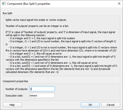
- Number of outputs
- Type in the number of output ports the component will have.
- Execution rate
- Type in the desired signal processing execution rate. This value must be compatible with other signal processing components of the same circuit: the value must be a multiple of the fastest execution rate in the circuit. There can be up to four different execution rates. To specify the execution rate, you can use either decimal (e.g. 0.001) or exponential values (e.g. 1e-3) in seconds. Alternatively, you can type in ‘inherit’ in which case the component will be assigned execution rate based on the execution rate of the components it is receiving input from.