Data Type Conversion
Description of the Data Type Conversion components in Schematic Editor, which converts the data type of the input signal into a selected data type.
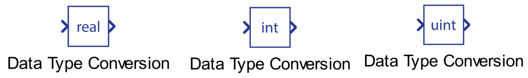
Component Icon
Description
The Data Type Conversion component converts the data type of the input signal into a selected data type.
For conversion to real type, the output is defined by the following equation:
For conversion to int type, the output is defined by the following equation:
For conversion to uint type, the output is defined by the following equation:
Ports
- Input (in)
- Supported types: uint, int and real.
- Vector support: yes.
- Output (out)
- Supported types: uint, int and real.
- The output type is dictated by the Output data type property.
- Vector support: yes.
- The vector length is inherited from the input signal
- Supported types: uint, int and real.
Properties
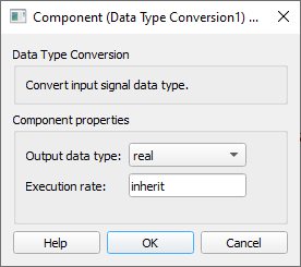
- Output data type
- Select the type to which the output signal will be converted. You can choose among the real, int, and uint type.
- Execution rate
- Type in the desired signal processing execution rate. This value must be compatible with other signal processing components of the same circuit: the value must be a multiple of the fastest execution rate in the circuit. There can be up to four different execution rates. To specify the execution rate, you can use either decimal (e.g. 0.001) or exponential values (e.g. 1e-3) in seconds. Alternatively, you can type in ‘inherit’ in which case the component will be assigned execution rate based on the execution rate of the components it is receiving input from.