Boolean Join
Description of the Boolean Join component in Schematic Editor, which converts boolean values into an unsigned integer signal.
Component Icon
Description
This component converts an input of Boolean values into a single unsigned integer signal or multiple unsigned integer signals using the weighted binary code.
The conversion is illustrated in the figure below.
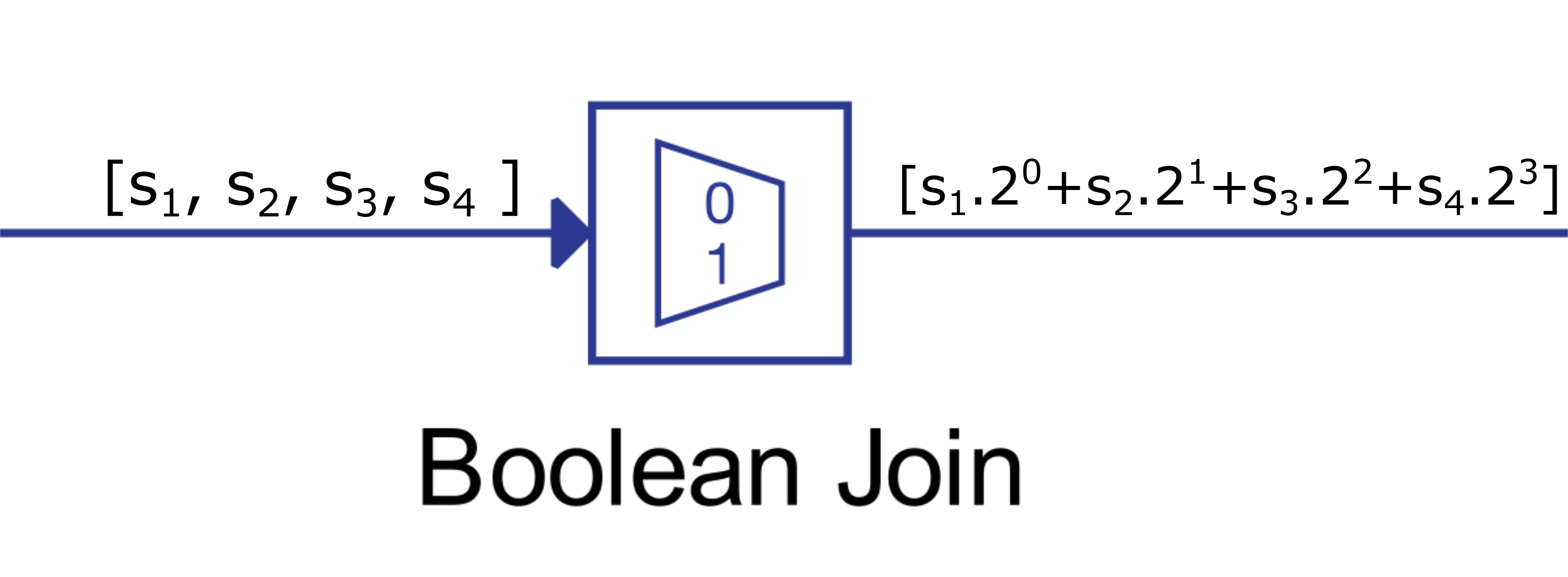
If the values of the input vector are different than Boolean values (i.e. 0 – False; 1 – True), they are first converted to Boolean by the following rule:
![]()
where sc represents the converter signal and si represents the input signal:
If the input signal is a vector with less than 32 elements, the output signal will be a scalar value. If the input signal is a vector with more than 32 elements, the output signal will be divided into two or more signals that represent the conversion of the input signal.
Ports
- Input “in” (in)
- Input signal connected composed of binary values.
- Supported types: uint, int and real.
- Vector support: yes.
- Input signal connected composed of binary values.
- Output (out)
- The output of the component, result of the conversion.
- Supported types: uint, int and real.
- Vector support: yes.
- The output length is calculated as the length of the input signal divided by 32.
- The output of the component, result of the conversion.
Properties
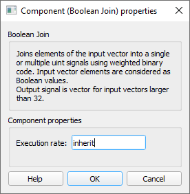
- Execution rate
- Type in the desired signal processing execution rate. This value must be compatible with other signal processing components of the same circuit: the value must be a multiple of the fastest execution rate in the circuit. There can be up to four different execution rates. To specify the execution rate, you can use either decimal (e.g. 0.001) or exponential values (e.g. 1e-3) in seconds. Alternatively, you can type in ‘inherit’ in which case the component will be assigned execution rate based on the execution rate of the components it is receiving input from.