Initial Settings
Description of the Initial Settings component in the Schematic Editor, which sets analog and/or digital outputs with corresponding signals from the model.
Description
The Initial Settings component enables signal assignment to analog and/or digital outputs of HIL devices within the Schematic Editor model in real-time/VHIL simulation. All corresponding settings of the analog and/or digital outputs can be set as well. Once the outputs are set and the model is compiled and loaded, Analog Outputs and Digital Outputs in the Model Settings section in SCADA will be set according to the Initial Settings parameters defined in the model.
In TyphoonSim, digital and analog signals are read from the internal virtual IO bus and can be individually routed. Hence, if some signal is sent to digital/analog ouput 1, it will appear on digital/analog input 1.
Properties
- HIL device ID
- In case multiple devices are connected, this property allows you to
select which device should be managed by the Initial Settings
component.
- In real-time/VHIL, it is only possible to choose signals from the selected device; otherwise, a compilation error will occur.
- In TyphoonSim, it is possible to choose signals from all devices that are being used and compilation will pass.
-
It is possible to have multiple Initial Settings components referencing the same HIL id. In this case:
- If different signals are set to the same output channel, an error will be reported.
- If the same signals are set to the same output, the compilation will pass but output will be set only once.
- In case multiple devices are connected, this property allows you to
select which device should be managed by the Initial Settings
component.
-
Output Settings (Tab)
- Analog Outputs (Tab)
- Name - select an analog output to send data to.
- Signal - selects a signal from the model to send data to the selected analog output. Available signals are Probe, Voltage/Current measurements, RMS Voltage/Current Measurements, Capacitors, Inductors, Nonlinear Inductor, Battery, PV Panel, Super Capacitor, Single Phase Constant Power Source, Current/Voltage Controlled Current/Voltage Source, Machine, and Contactors Signals.
- Scaling - factor that should be multiplied by the original signal value to get the desired measured value at the selected analog output.
- Offset - value that should be added to the original signal value to get the desired measured value at the selected analog output.
- Enable Limit - allows voltage limiting.
Available on HIL101, HIL404, HIL602+, HIL604, HIL506, and HIL606 for real-time simulation.
- Lower/Upper Limit - sets limits for voltage.
- Digital Outputs (Tab)
- Name - select a digital output to send data to.
- Signal - selects a signal from the model to send data to the selected digital output. Available signals are Digital Probe, comparator outputs of Voltage/Current Measurements, PWM Modulator, and machine signals.
- Invert - inverts the assigned signals when enabled.
- SW Control- Enable checkbox defines the control mode. If True, the digital output value is defined by the value button with possible values either 0 or 1, otherwise the value is defined by the assigned signal.
- Analog Outputs (Tab)
- Switching Blocks (Tab)
-
- Switch Name - select a digital output to send data to.
- SW control - you can override the external control value of the switch by setting the software control checkbox to True.
- SW Value - the control signal value is defined by the value 1(ON) or 0 (OFF) for each switch.
HIL SCADA (Real-time/VHIL)
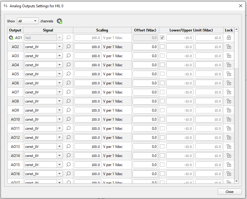
All channels that are set from the Schematic Editor model through the Output Settings component are marked with an icon next to the channel number on the left. By default, these channels are locked. It is possible to unlock them and override the settings imported from the Schematic Editor model in the Model Settings in SCADA.
Output settings from the model can be restored by using the Initial Settings Restore button in Analog/Digital Output Settings in HIL SCADA.
Setting Initial Settings properties through API
To set Initial settings properties through API you will need to define a dictionary with desired values.
For example, if you have a Digital Probe in your model, you can set the Initial Settings digital output like this:
                initial_settings = mdl.get_item("Output Settings", parent=comp_handle, item_type=ITEM_COMPONENT)

                digital_dict = {
                'do_channel': "1",
                'signal': "Digital Probe",
                'invert': "True",
                'sw_control': "True",
                'sw_value': "1"
                }
                mdl.set_property_value(mdl.prop(initial_settings, "digital_outputs"), [digital_dict])
In the case of Voltage measurements, you can set the analog output with:
                initial_settings = mdl.get_item("Output Settings", parent=comp_handle, item_type=ITEM_COMPONENT)

                analog_dict = {
                'ao_channel': "1",
                'signal': "Va1",
                'scaling': "300",
                'offset' : "0",
                'enable_limit' : 'True',
                'lower_limit' : "-100",
                'upper_limit': "100"
                }
                mdl.set_property_value(mdl.prop(initial_settings, "analog_outputs"), [analog_dict])
A special case of Voltage measurements is when the fullbandwidth option is enabled and you want to set multiple analog outputs at once. Then, you can set the analog output as follows:
                initial_settings = mdl.get_item("Output Settings", parent=comp_handle, item_type=ITEM_COMPONENT)

                analog_dict1 = {
                'ao_channel': "1",
                'signal': "Va1.fullbandwidth",
                'scaling': "300",
                'offset' : "0",
                'enable_limit' : 'True',
                'lower_limit' : "-100",
                'upper_limit': "100"
                }

                analog_dict2 = {
                'ao_channel': "2",
                'signal': "Va1",
                'scaling': "300",
                'offset' : "0",
                'enable_limit' : 'True',
                'lower_limit' : "-100",
                'upper_limit': "100"
                }
                mdl.set_property_value(mdl.prop(initial_settings, "analog_outputs"), [analog_dict1, analog_dict2])
You can set outputs for machines, for example an Induction Machine with Double Cage, in this way:
                initial_settings = mdl.get_item("Output Settings", parent=comp_handle, item_type=ITEM_COMPONENT)

                analog_dict = {
                'ao_channel': "1",
                'signal': "indm machine.Stator.i_a",
                'scaling': "300",
                'offset' : "0",
                'enable_limit' : 'True',
                'lower_limit' : "-100",
                'upper_limit': "100"
                }
                mdl.set_property_value(mdl.prop(initial_settings, "analog_outputs"), [analog_dict])
In the same way you can set outputs for machines involves electrical and mechanical signals:
                initial_settings = mdl.get_item("Output Settings", parent=comp_handle, item_type=ITEM_COMPONENT)

                analog_dict1 = {
                'ao_channel': "1",
                'signal': "indm machine.i_als",
                'scaling': "300",
                'offset' : "0",
                'enable_limit' : 'True',
                'lower_limit' : "-100",
                'upper_limit': "100"
                }

                analog_dict2 = {
                'ao_channel': "2",
                'signal': "indm machine.mechanical speed",
                'scaling': "300",
                'offset' : "0",
                'enable_limit' : 'True',
                'lower_limit' : "-100",
                'upper_limit': "100"
                }
                mdl.set_property_value(mdl.prop(initial_settings, "analog_outputs"), [analog_dict1, analog_dict2])