Symmetrical Components
Description of the Symmetrical Components component in Schematic Editor, which transforms three-phase systems to sets of symmetrical phasors.
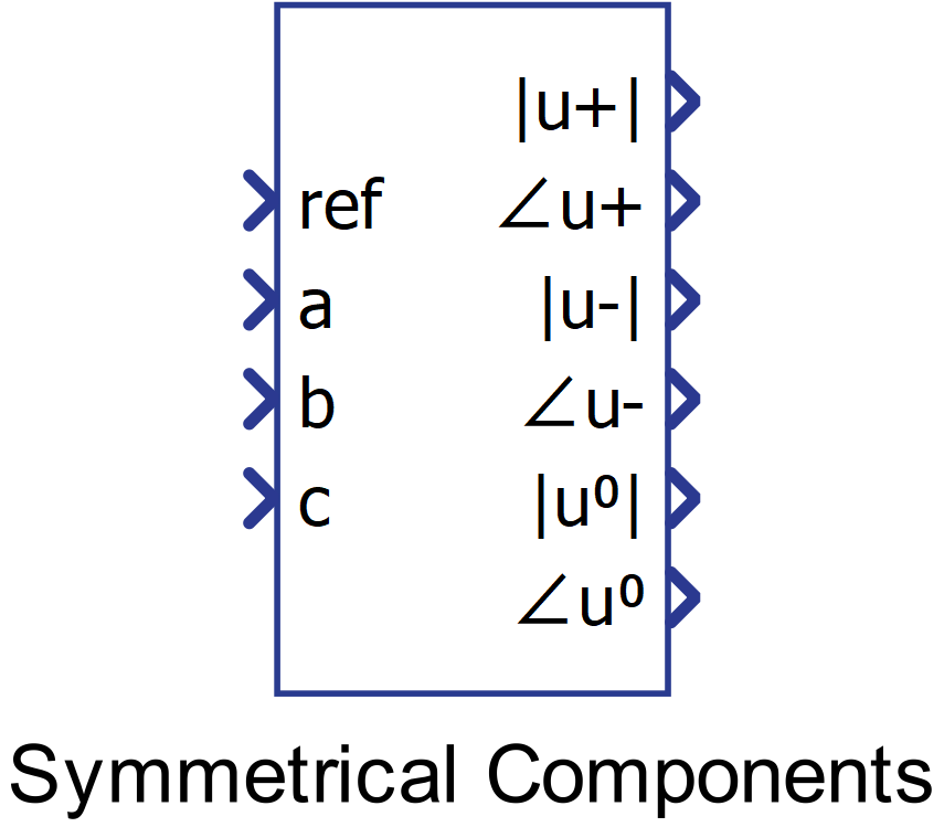
Component Icon
Description
Performs transformation of a three-phase system to sets of symmetrical phasors.
The input to the component is a three-phase signal and a reference signal used for calculating the phase. The component outputs three sets of symmetrical phasors: positive sequence, negative sequence and the zero sequence. Each set consists of RMS and phase values.
As a first step, the input signals are transformed from the time to the complex domain. After that, Fortescue’s transformation is performed to calculate the positive, negative and zero sequence phasor using the following formulas:
a representing a rotating phasor:
with real and imag representing the phasor’s real part and imaginary part, respectively.
The RMS and phase values are calculated using a fixed or variable frequency, depending on chosen parameter values (see Frequency source).
To ensure the correct output of the component, it is necessary to ensure that .
Ports
- ref (in)
- Ref input is used to connect the reference signal for phase calculation. Usually, the
signal a is connected to this terminal.
- Supported types: uint, int, real.
- Vector support: no.
- Ref input is used to connect the reference signal for phase calculation. Usually, the
signal a is connected to this terminal.
- a (in)
- Input a of the component, corresponding to the three-phase abc system.
- Supported types: uint, int, real.
- Vector support: no.
- Input a of the component, corresponding to the three-phase abc system.
- b (in)
- Input b of the component, corresponding to the three-phase abc system.
- Supported types: uint, int, real.
- Vector support: no.
- Input b of the component, corresponding to the three-phase abc system.
- c (in)
- Input c of the component, corresponding to the three-phase abc system.
- Supported types: uint, int, real.
- Vector support: no.
- Input c of the component, corresponding to the three-phase abc system.
- f (in)
- Input f of the component, corresponding to the frequency of the three-phase abc system
(if "External" frequency source is chosen).
- Supported types: uint, int, real.
- Vector support: no.
- Input f of the component, corresponding to the frequency of the three-phase abc system
(if "External" frequency source is chosen).
- |u+|
- This terminal outputs the RMS value of the positive sequence phasor.
- Supported types: real.
- Vector support: no.
- This terminal outputs the RMS value of the positive sequence phasor.
- ∠u+
- This terminal outputs the phase angle value of the positive sequence phasor (compared to
referent signal).
- Supported types: real.
- Vector support: no.
- This terminal outputs the phase angle value of the positive sequence phasor (compared to
referent signal).
- |u-|
- This terminal outputs the RMS value of the negative sequence phasor.
- Supported types: real.
- Vector support: no.
- This terminal outputs the RMS value of the negative sequence phasor.
- ∠u-
- This terminal outputs the phase angle value of the negative sequence phasor (compared to
referent signal).
- Supported types: real.
- Vector support: no.
- This terminal outputs the phase angle value of the negative sequence phasor (compared to
referent signal).
- |u0|
- This terminal outputs the RMS value of the zero sequence phasor.
- Supported types: real.
- Vector support: no.
- This terminal outputs the RMS value of the zero sequence phasor.
- ∠u0
- This terminal outputs the phase angle value of the zero sequence phasor (compared to
referent signal).
- Supported types: real.
- Vector support: no.
- This terminal outputs the phase angle value of the zero sequence phasor (compared to
referent signal).
Properties
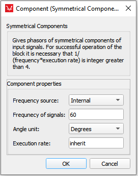
- Frequency source
- If the chosen value is "Internal", the component calculates the output using a fixed frequency value. If "External" value is used, the additional input will be created and a frequency value should be provided through signal processing.
- Frequency of the signals
- Type in the input signals frequency using this property. The component calculates the output using a fixed frequency value.
- Angle unit
- Angle can be expressed in radians or degrees.
- Execution rate
- Type in the desired signal processing execution rate. This value must be compatible with other signal processing components of the same circuit: the value must be a multiple of the fastest execution rate in the circuit. There can be up to four different execution rates. To specify the execution rate, you can use either decimal (e.g. 0.001) or exponential values (e.g. 1e-3) in seconds. Alternatively, you can type in ‘inherit’ in which case the component will be assigned execution rate based on the execution rate of the components it is receiving input from.