Phase Difference
Description of the Phase Difference component in Schematic Editor, which outputs the difference between the phases of the input signal in comparison with the reference signal.
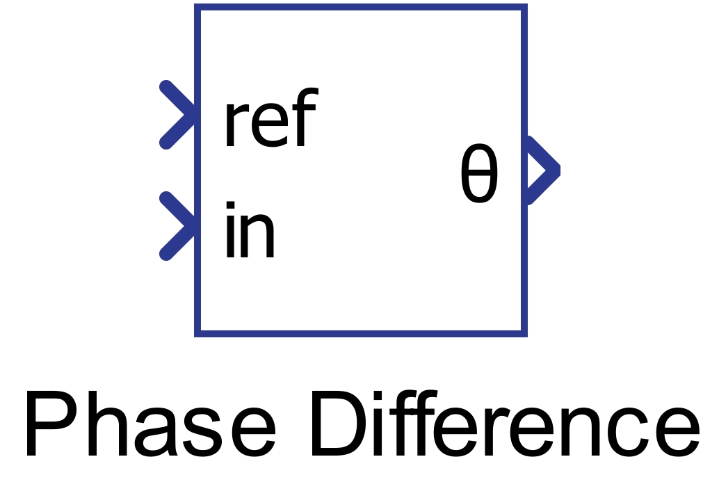
Component Icon
Description
Phase difference component outputs the difference between the phases of the input signal in comparison with the reference signal.
Figure 2 illustrates the behavior of the phase difference component.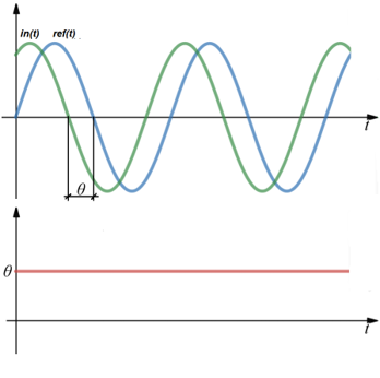
Phase shift (θ) in comparison to the input signal (in) with the reference signal (ref). In the bottom waveform, the output of the Phase Difference component is presented, which is the measured phase θ between these two signals in degrees.
Ports
- Ref (in)
- The reference signal for the angle measurement.
- Supported types: real.
- Vector support: no.
- The reference signal for the angle measurement.
- In (in)
- Input signal whose phase difference is measured.
- Supported types: real.
- Vector support: no.
- Input signal whose phase difference is measured.
- Output (out)
- Value of the phase difference, in degrees.
- Supported types: real.
- Vector support: no.
- Value of the phase difference, in degrees.
Properties
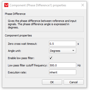
- Zero cross wait timeout
- Type in the maximal period to wait for zero-crossing detection. This method uses zero-crossing detection to measure the period of signals. If the input signals period is longer than the timeout value, the phase will not be correctly measured.
- Angle unit
- The phase difference angle can be expressed in radians or degrees.
- Enable low pass filter
- Check if you want to enable low pass filter
- Low pass filter cutoff frequency
- Type in the frequency for low pass filter. It is used to improve zero crossing detection.
- Execution rate
- Type in the desired signal processing execution rate. This value must be compatible with other signal processing components of the same circuit: the value must be a multiple of the fastest execution rate in the circuit. There can be up to four different execution rates. To specify the execution rate, you can use either decimal (e.g. 0.001) or exponential values (e.g. 1e-3) in seconds. Alternatively, you can type in ‘inherit’ in which case the component will be assigned execution rate based on the execution rate of the components it is receiving input from.