Single Phase Power Meter
Description of the Single Phase Power Meter component in Schematic Editor, which computes active and reactive power of a single-phase circuit.
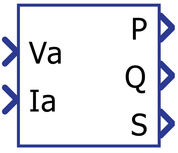
Component Icon
Description
Single phase power meter component computes active and reactive power of a single-phase circuit.
The component is designed as a composite, and its implementation is shown in Figure 2.
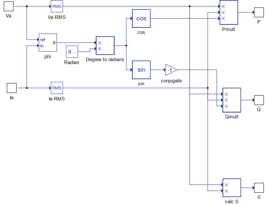
The RMS values of both voltage and current are calculated first, and after that power output is defined in following manner:
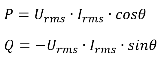
where ϴ represents the phase difference between the voltage and current signal phasors.
The RMS values and phase difference are calculated using the input signal frequency which is either specified by the user as a property of component or automatically calculated with an internal PLL control system. Considering that, this component is suitable for power measurement for steady states and for the pure sinusoidal conditions.
- Input Filter
- In order to improve accuracy of the results, the input signal is filtered using an
exponential moving average filter. The filtered signal is used to calculate the phase
of the input current to the input voltage, hence, increasing the accuracy of the
results for signals with high harmonic content and/or multiple zero crossings.
The filter cutoff frequency, set by the user in is Input filter cutoff frequency, is defined as the frequency where the amplitude of the input signal drops by -3 dB.
- In order to improve accuracy of the results, the input signal is filtered using an
exponential moving average filter. The filtered signal is used to calculate the phase
of the input current to the input voltage, hence, increasing the accuracy of the
results for signals with high harmonic content and/or multiple zero crossings.
Ports
- Va (in)
- Instantaneous voltage value.
- Supported types: int, uint, real.
- Vector support: no.
- Instantaneous voltage value.
- Ia (in)
- Instantaneous current value.
- Supported types: int, uint, real.
- Vector support: no.
- Instantaneous current value.
- P (out)
- Active power value.
- Supported types: real.
- Vector support: no.
- Active power value.
- Q (out)
- Reactive power value.
- Supported types: real.
- Vector support: no.
- Reactive power value.
- S (out)
- Apparent power value.
- Supported types: real.
- Vector support: no.
- Apparent power value.
Properties
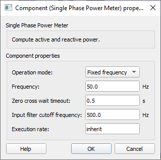
- Operation mode
- Chose the operation mode of the single phase power measurement. Available options are: "Fixed frequency" and "PLL based". PLL based operation mode will automatically find the frequency of the input signal with the use of a PLL (Phase Locked Loop) control system.
- Frequency
- Type in the frequency of the input signal.
- This parameter is only visible when Operation mode is set to "Fixed frequency"
- Type in the frequency of the input signal.
- Zero cross wait timeout
- Type in the period used as base to calculate the zero crossing of input signals. If the frequency of the input signal is small enough such that the timeout period is bigger than the input signal period, the phase of the input signals is not correctly measured.
- Input filter cutoff frequency
- Type in the cutoff frequency of the exponential moving average filter of the input signals.
- Execution rate
- Type in the desired signal processing execution rate. This value must be compatible with other signal processing components of the same circuit: the value must be a multiple of the fastest execution rate in the circuit. There can be up to four different execution rates. To specify the execution rate, you can use either decimal (e.g. 0.001) or exponential values (e.g. 1e-3) in seconds. Alternatively, you can type in ‘inherit’ in which case the component will be assigned execution rate based on the execution rate of the components it is receiving input from.