JK Flip Flop
Description of the JK Flip Flop component in Schematic Editor, which implements the functionality of the JK Flip Flop sequential logic.
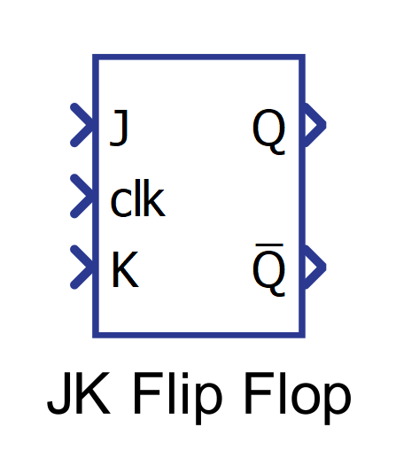
Component Icon
Description
The JK Flip Flop component implements the functionality of the JK Flip Flop sequential logic.
Every time a rising/falling edge is detected on the clock signal, the Flip Flop state is calculated based on the combination of J and K inputs. The J input can be viewed as a Set input and K input as a Reset input. If J is active when the clock edge is detected, the Flip Flop will store the value 1. If K is active when the clock edge is detected, the JK Flip Flop component will store the value 0. A special case is when both J and K are active: in this case, the Flip Flop state will toggle its value between 0 and 1 on each clock edge. The state is available on the Q terminal.
The output of JK Flip Flop can be described using the truth table displayed in Table 1.| J | K | Clock | Q | Q̅ |
| 0 | 0 | edge (↑ or ↓) | No change | No change |
| 1 | 0 | edge (↑ or ↓) | 1 | 0 |
| 0 | 1 | edge (↑ or ↓) | 0 | 1 |
| 1 | 1 | edge (↑ or ↓) | Toggle | Toggle |
| X | X | No edge | No change | No change |
X denotes a “don’t care” position, which means that the input signal is irrelevant.
You can choose if sampling is done on the rising or on the falling clock edge using the Sampling edge property.
The JK Flip Flop component stores the value as Boolean, as far as the input values are concerned. Every number that is not 0 will be treated as 1.
Q̅ output is an inverted state output.
Ports
- Input J (in)
- Input signal Set
- Supported types: uint, int and real.
- Vector support: yes.
- Input signal Set
- Input K (in)
- Input signal Reset
- Supported types: uint, int and real.
- Vector support: yes.
- Input signal Reset
- Q (out)
- The output of the component, according to the Truth table.
- Supported types: uint, int and real.
- The output type is inherited from the input signal.
- Vector support: yes.
- The vector length is inherited from the input signal or calculated using property value lengths. If the property is defined as a vector, the output will be a vector of the same length.
- Supported types: uint, int and real.
- The output of the component, according to the Truth table.
- Q̅ (out)
- The inverse of the output Q, according to the Truth table.
- Supported types: uint, int and real.
- The output type is inherited from the input signal.
- Vector support: yes.
- The vector length is inherited from the input signal or calculated using property value lengths. If the property is defined as a vector, the output will be a vector of the same length.
- Supported types: uint, int and real.
- The inverse of the output Q, according to the Truth table.
Properties
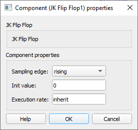
- Sampling edge
- Select the edge of the clock signal that will be used for sampling.
- Initial Value
- Type in the initial value of the JK Flip Flop component. The property can be scalar or vector.
- Execution rate
- Type in the desired signal processing execution rate. This value must be compatible with other signal processing components of the same circuit: the value must be a multiple of the fastest execution rate in the circuit. There can be up to four different execution rates. To specify the execution rate, you can use either decimal (e.g. 0.001) or exponential values (e.g. 1e-3) in seconds. Alternatively, you can type in ‘inherit’ in which case the component will be assigned execution rate based on the execution rate of the components it is receiving input from.