PID Controller
Description of the PID Controller components in Schematic Editor, which implement a discrete-time PID control algorithm.
Component Icon
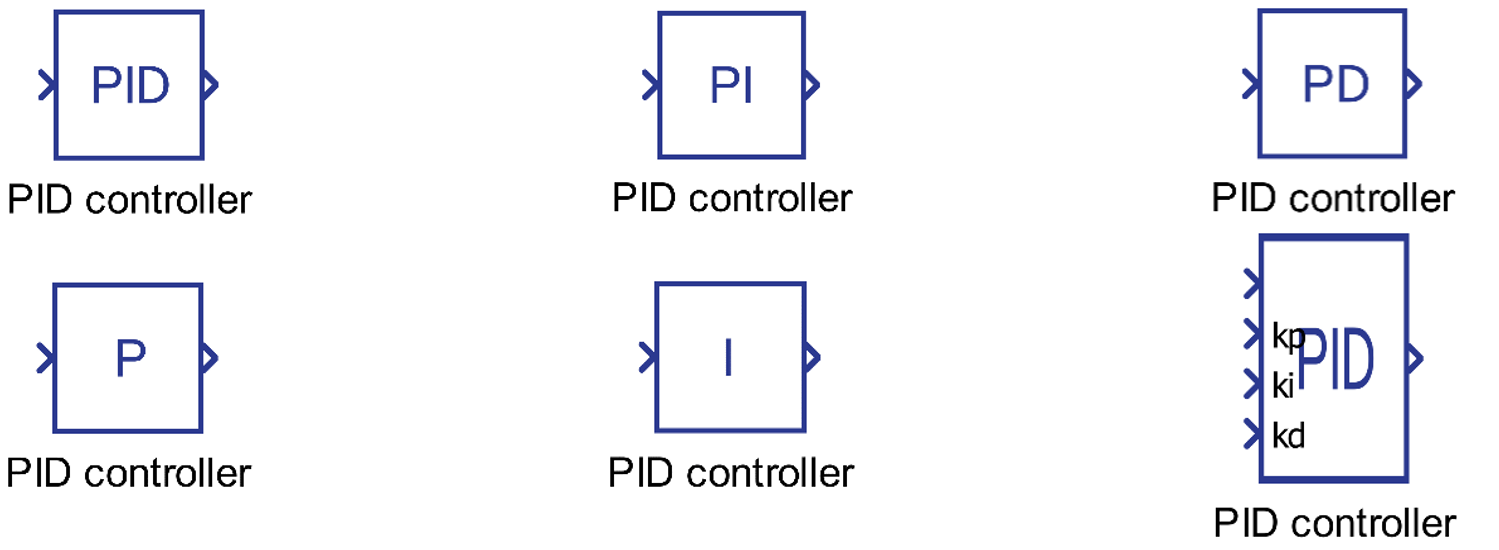
Description
The PID block implements discrete-time PID control algorithm with optional anti-windup feature. Anti-windup mechanism is based on conditional integration strategy.
Kp, Ki, and Kd gains should be informed in the continuous time domain and later, the discretization is done using Euler method.
Figure 2 illustrates the generic representation.
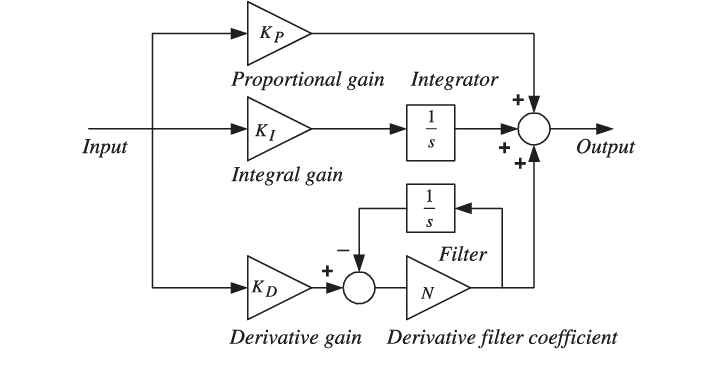
Kp, Ki and Kd gains can be fixed and specified using corresponding properties, or can be specified using a signal form the model. If the gain source is defined as external, additional terminal is created on the component to connect the desired signal.
If the limit is enabled, the output of the component will be limited to the defined values.
Anti-windup determines whether the integrator part of the PID continues to integrate the error signal when the output signal is saturated.
Ports
- In (in)
-
Input of the component. Generally, this is the error signal (difference between a reference signal and the measured value) of a control system.
- Supported types: uint, int and real.
- Vector support: no.
-
- kp (in)
-
Value of the proportional gain of the PID block when Kp source is set as “external”.
- Supported types: uint, int and real.
- Vector support: no.
- Dynamically created when Kp source property is defined as “external”.
-
- ki (in)
-
Value of the integral gain of the PID block when Ki source is set as “external”.
- Supported types: uint, int and real.
- Vector support: no.
- Dynamically created when Ki source property is defined as “external”.
-
- kd (in)
-
Value of the derivative gain of the PID block when Kd source is set as “external”.
- Supported types: uint, int, and real.
- Vector support: no.
- Dynamically created when Kd source property is defined as “external”.
-
- Out (out)
-
Output signal of the component.
- Supported types: uint, int and real.
- The output type is determined by the Signal type property.
- Vector support: no.
- Supported types: uint, int and real.
-
Properties
- Controller type
- Choose the type of the control that the block will calculate. It can be “P”, “I”, “PI”, “PD”, or “PID”.
- Kp
- Type in the gain value to be applied to the proportional gain of the PID control block.
- Kp source
- Choose the source for the parameter Kp. It can be “internal” or “external”. This parameter defines whether the gain value to be applied to the proportional gain of the PID control block is set internally or externally. In case it is set externally, an additional input is displayed in the block.
- Ki
- Type in the gain value to be applied to the integrator gain of the PID control block.
- Ki source
- Choose the source for the parameter Ki. It can be “internal” or “external”. This parameter defines whether the gain value to be applied to the integrator gain of the PID control block is set internally or externally. In case it is set externally, an additional input is displayed in the block.
- Integrator Initial Condition
- Type in the initial condition to be applied to the integrator parcel of the PID control block
- Kd
- Type in the gain value to be applied to the differentiator gain of the PID control block.
- Kd source
- Choose the source for the parameter Kd. It can be “internal” or “external”. This parameter defines whether the gain value to be applied to the differentiator gain of the PID control block is set internally or externally. In case it is set externally, an additional input is displayed in the block.
- Filter coefficient
Type in the filter coefficient which is used to implement the derivative action since it is not possible to implement a transfer function like . The implementation of a derivative action, therefore, is done as in:
Hence, if N is sufficiently large, tends to the ideal implementation of a derivative action .
- Filter initial condition
- Type in the initial condition of the derivative filter.
- Signal out type
- Choose the type of the control signal of the PID block. It can be “real”, “int”, “uint”, or “inherit”.
- Limit
- Choose whether the output signal of the PID block is saturated when reaches a determined upper or low limit. It can be set as “True” or “False”.
- Upper Saturation limit
- Type in the upper limit of the output signal of the PID block. This parameter is editable if Limit is set as “True”.
- Lower Saturation limit
- Type in the lower limit of the output signal of the PID block. This parameter is editable if Limit is set as “True”.
- Anti-windup
- Choose whether “Anti-windup” action takes place (True) or not (False). This parameter determines whether the integrator part of the PID continues to integrate the error signal when the output signal is saturated.
- Execution rate
- Type in the desired signal processing execution rate. This value must be compatible with other signal processing components of the same circuit: the value must be a multiple of the fastest execution rate in the circuit. There can be up to four different execution rates. To specify the execution rate, you can use either decimal (e.g. 0.001) or exponential values (e.g. 1e-3) in seconds. Alternatively, you can type in ‘inherit’ in which case the component will be assigned execution rate based on the execution rate of the components it is receiving input from.
- Tunable
 Tunable is ignored in
TyphoonSim and changing its value will not affect TyphoonSim
simulation at all.
Tunable is ignored in
TyphoonSim and changing its value will not affect TyphoonSim
simulation at all.- Enables run-time tuning of the selected component. Depending on the selected type of controller, this setting will allow you to change values for Kp, Ki, Kd, Upper saturation limit, and Lower saturation limit during simulation without the need to recompile the model. Tunable properties are available in HIL SCADA in Model Explorer.