RMS Value
Description of the RMS Value component in Schematic Editor, which outputs the root mean square (RMS) value of an AC signal.
Component icon

Description
The RMS value component outputs the root mean square (RMS) value of an AC signal.
If the input signal of the RMS value component is given by x(t), the output signal, y(t), of the RMS value component is given by:
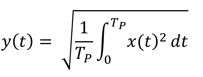
Where TP is the period of the input signal x(t). The period is calculated using either PLL based mode or Fixed frequency mode.
In the PLL based mode, the period is calculated based on zero-crossing. That is, sample times are measured by the gap between two zero values of the input signal. In Fixed frequency mode, the period is calculated based on the Fundamental frequency property value. For more details, see Operation mode
Ports
- Input (in)
- AC input signal.
- Supported types: real.
- Vector support: Yes.
- AC input signal.
- Output (out)
- RMS value of the input signal.
- Supported types: real.
- Vector support: Yes.
- RMS value of the input signal.
Properties
- Operation mode
- Select the operation mode utilized by the RMS to calculate the RMS
value. The RMS value component supports two operation modes:
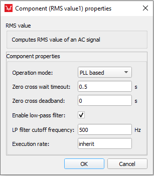
- PLL based – this mode calculates the input signal period by detecting the zero-crossing of the signal. If the zero-crossing does not occur within the Zero cross wait timeout, that timeout period will be used as a period to calculate the RMS value.
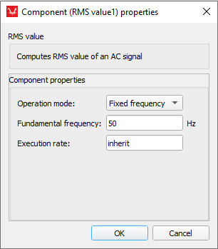
- Fixed frequency – the signal period is calculated based on the Fundamental frequency value.
- Select the operation mode utilized by the RMS to calculate the RMS
value. The RMS value component supports two operation modes:
- Zero cross wait timeout
- Type in the maximum value for the time interval in which a zero crossing of the input signal must occur.
- Fundamental frequency
- Type in the value of the fixed frequency to calculate the signal period. Visible only if operation mode is set to Fixed frequency
- Zero cross deadband
- This property value prevents the component from registering multiple zero crossing events caused by signal harmonic distortion. If multiple zero crossings are registered inside the time interval specified by value of this property, only the first one will be considered. Visible only if the operation mode is set to PLL based.
- Enable low-pass filter
- If checked, the low-pass filter will be applied to the signal that the PLL uses for period detection. This filtering prevents signal distortion from causing multiple zero-crossing events, which are used for estimating the fundamental frequency. However, using this low-pass filter will not influence measurements used for RMS calculation but only for detecting the period of the signal.Visible only if the operation mode is set to PLL based.
- LP filter cutoff frequency
- Frequency of the low-pass filter. Visible if low-pass filter is enabled.
- Execution rate
- Type in the desired signal processing execution rate. This value must be compatible with other signal processing components of the same circuit: the value must be a multiple of the fastest execution rate in the circuit. There can be up to four different execution rates. To specify the execution rate, you can use either decimal (e.g. 0.001) or exponential values (e.g. 1e-3) in seconds. Alternatively, you can type in ‘inherit’ in which case the component will be assigned execution rate based on the execution rate of the components it is receiving input from.