SVPWM (Space Vector Pulse Width Modulation) reference generator
Description of the SVPWM References Generator component in Schematic Editor, which generates PWM reference signals for three-phase two-Level inverters using the space-vector pulse width modulation (SVPWM) technique.
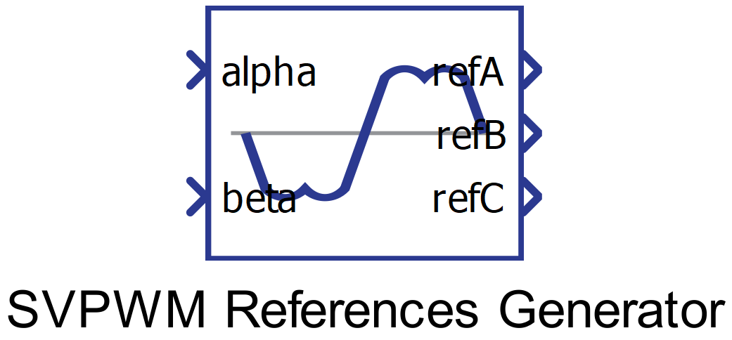
Component Icon
Description
This block generates PWM reference signals for three-phase two-Level inverters using the space-vector pulse width modulation (SVPWM) technique.
- upper switch in leg is active – state 1;
- lower switch in leg is active – state 0,
This gives us eight possible basic space vectors, which are given in table 1. Vectors from U1 to U6 are different non-zero vectors, while vectors U7 and U8 represent two zero vectors (All three upper switches, or all three lower switches active).
| Vector | Leg 1 state | Leg 2 state | Leg 3 state |
| U1 | 1 | 0 | 0 |
| U2 | 1 | 1 | 0 |
| U3 | 0 | 1 | 0 |
| U4 | 0 | 1 | 1 |
| U5 | 0 | 0 | 1 |
| U6 | 1 | 0 | 1 |
| U7 | 0 | 0 | 0 |
| U8 | 1 | 1 | 1 |
This is illustrated in Figure 2:
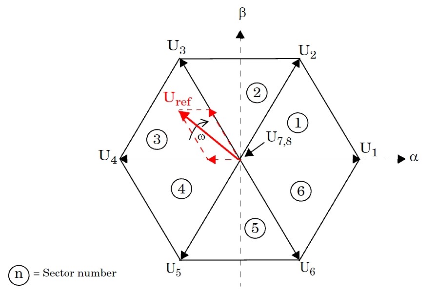
In every PWM period, the reference voltage vector is obtained by using two adjacent non-zero space vectors, depending on the sector in which the reference vector is located (e.g. in Figure 2 the reference vector is in sector 3, so space vectors U3 and U4 are used). These two space vectors are being used for a certain amount of time and a null vector (U7 or U8) is used for the remaining time.
Generated reference signals should be used with the 3-channel PWM modulator component to implement full SVPWM operation. The execution rate should be set to the same value as for the PWM Modulator period. Input and output signals have a range of -1.0 to 1.0.
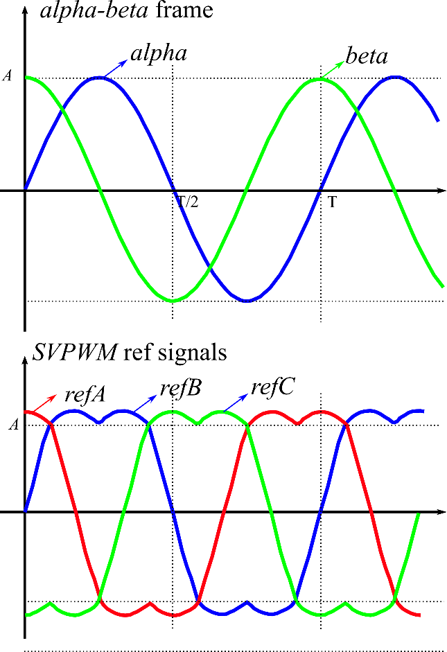
Figure 3 illustrates the generation of three-phase SVPWM reference waveforms according to the alpha-beta reference input.
Ports
- alpha (in)
- Alpha signal of the component used to generate the signal for the modulator of a
three-phase SVPWM modulation system.
- Supported types: uint, int, real.
- Vector support: no.
- Alpha signal of the component used to generate the signal for the modulator of a
three-phase SVPWM modulation system.
- beta (in)
- Beta signal of the component used to generate the signal for the modulator of a
three-phase SVPWM modulation system.
- Supported types: uint, int, real.
- Vector support: no.
- Beta signal of the component used to generate the signal for the modulator of a
three-phase SVPWM modulation system.
- refA (out)
- Reference for phase A of a three-phase SVPWM modulator.
- Supported types: real.
- Vector support: no.
- Reference for phase A of a three-phase SVPWM modulator.
- refB (out)
- Reference for phase B of a three-phase SVPWM modulator.
- Supported types: real.
- Vector support: no.
- Reference for phase B of a three-phase SVPWM modulator.
- refC (out)
- Reference for phase C of a three-phase SVPWM modulator.
- Supported types: real.
- Vector support: no.
- Reference for phase C of a three-phase SVPWM modulator.
Properties
- Execution rate
- Type in the desired signal processing execution rate. This value must be compatible with other signal processing components of the same circuit: the value must be a multiple of the fastest execution rate in the circuit. There can be up to four different execution rates. To specify the execution rate, you can use either decimal (e.g. 0.001) or exponential values (e.g. 1e-3) in seconds. Alternatively, you can type in ‘inherit’ in which case the component will be assigned execution rate based on the execution rate of the components it is receiving input from.