Gray Coder
Description of the Gray Coder component in Schematic Editor, which converts the unsigned integer value of an input signal to Gray code.
Component Icon
Description
The Gray Coder component converts the unsigned integer value of the input signal to Gray code.
Gray code is an ordering of the binary numeral system such that two successive values differ in only one bit.
The output value is calculated by performing the exclusive OR operation between the input value and the input value shifted to the right by one bit.
out value = in valueb ⊕ (in valueb >> 1)
| Decimal | Binary | Gray |
|---|---|---|
| 0 | 0000 | 0000 |
| 1 | 0001 | 0001 |
| 2 | 0010 | 0011 |
| 3 | 0011 | 0010 |
| 4 | 0100 | 0110 |
| 5 | 0101 | 0111 |
| 6 | 0110 | 0101 |
| 7 | 0111 | 0100 |
| 8 | 1000 | 1100 |
| 9 | 1001 | 1101 |
| 10 | 1010 | 1111 |
| 11 | 1011 | 1110 |
| 12 | 1100 | 1010 |
| 13 | 1101 | 1011 |
| 14 | 1110 | 1001 |
| 15 | 1111 | 1000 |
The length of the gray code is defined through the Bit width property value. This value determines if the input signal value will be limited.
- The value of the input signal is always converted to an unsigned integer value before the conversion to gray code is performed. If the input signal is negative, the value is limited to 0. If the value is real, the decimal part of the number is ignored (ex. 5.75 is trimmed to 5).
- The maximal value of the input signal that can be converted to gray code is determined by the value 2Bit width - 1 (if the bit width is 4, the maximal input value is 15).
- If the value of the input signal is greater than the 2Bit width - 1, the value is limited to the maximal number that can be represented by the expression. For example, if the bit width is 4 and the input value is 20, the value will be limited to 15.
The output signal will be a vector with the length of Bit width , where the out[0] is the Least Significant Bit (LSB) and out[Bit width - 1] is the Most Significant Bit (MSB) of the gray code.
Example: Let us consider an example where the bit width of the gray code is 4 and the input value is 35. Because the largest number that can be represented with 4 bits is 15, the input value will be limited to 15 and converted. The conversion will be:
out value = 1111b⊕ (1111b >> 1) = 1111b ⊕ 0111b = 1000b
And the output vector of the Gray Coder component will be:
out[0] = 0
out[1] = 0
out[2] = 0
out[3] = 1
Ports
- Input (in)
- Supported types: real, int, uint.
- Vector support: no.
- Output (out)
- Supported types: real, int, uint.
- The type is inherited from the input signal type.
- Vector support: no.
- The vector length is determined by the Bit width property value
- Supported types: real, int, uint.
Properties
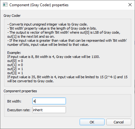
- Bit width
- Type in the length of the Gray code in bits.
- Execution rate
- Type in the desired signal processing execution rate. This value must be compatible with other signal processing components of the same circuit: the value must be a multiple of the fastest execution rate in the circuit. There can be up to four different execution rates. To specify the execution rate, you can use either decimal (e.g. 0.001) or exponential values (e.g. 1e-3) in seconds. Alternatively, you can type in ‘inherit’ in which case the component will be assigned execution rate based on the execution rate of the components it is receiving input from.