FLL Sync
Description of the Frequency Locked Loop (FLL) synchronization component in Schematic Editor, which generates an output signal which its phase is related to the phase of an input signal for single-phase systems.
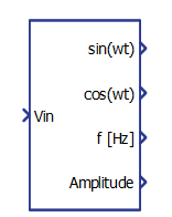
Component Icon
Description
The single-phase FLL Synchronization component is useful for generating the grid synchronization signals for grid-connected converter control, in a stationary (αβ) frame. These signals can also be converted to the synchronous frame (dq) and used as a control reference.
The FLL Sync component algorithm is composed of two main blocks, as shown in Figure 2. The first is the Second Order Generalized Integrator (SOGI) and the other is the Frequency Locked Loop.
The SOGI generates the αβ signals sin(wt) and cos(wt). cos(wt) is always lagged 90º behind the input Vin, while the FLL provides the frequency value signal for correct synchronization.
There are only two parameters set inside the FLL synchronization algorithm, and their values are adjusted to , as suggested in References [1].
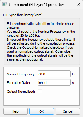
It is necessary to provide the nominal grid frequency and the sampling time for the algorithm to work properly. Additionally, a checkbox provides the option to generate a normalized signal at the output. These options can be set in the Component Properties, as shown in Figure 3.
FLL sync implementation was made by means of a C function following the code structure presented in References [2].
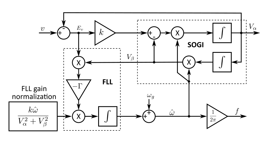
The two output signals Vα and Vβ have the same amplitude only in the case when the frequency of the input signal and the resonance frequency of the SOGI are equal. The error signal Ev and the voltage Vβ are in phase when input frequency is lower than SOGI resonance frequency, and they are in counter-phase when the input frequency is greater than SOGI resonance frequency [1]. Therefore, the result of the product Vβ and Ev is suitable to be used as an error signal for adjusting the SOGI resonance frequency, which is done by the FLL block.
Ports
- Vin (in)
- Sinusoidal input of the single-phase system from which the phase and frequency is
intended to be extracted.
- Supported types: real.
- Vector support: no.
- Sinusoidal input of the single-phase system from which the phase and frequency is
intended to be extracted.
- sin(wt) (out)
- Output signal of the component related to the direct component of the αβ-frame
input.
- Supported types: real.
- Vector support: no.
- Output signal of the component related to the direct component of the αβ-frame
input.
- cos(wt) (out)
- Output signal of the component related to the quadrature component of the αβ-frame
input.
- Supported types: real.
- Vector support: no.
- Output signal of the component related to the quadrature component of the αβ-frame
input.
- f[Hz] (out)
- Frequency (Hz) of the single-phase input system.
- Supported types: real.
- Vector support: no.
- Frequency (Hz) of the single-phase input system.
- Amplitude (out)
- Amplitude of the output signals,
.
- Supported types: real.
- Vector support: no.
- Amplitude of the output signals,
.
Properties
- Grid frequency
- Type in the nominal frequency of the input signal. Typical values are 60.0 or 50.0 Hz.
- Output Normalized
-
If checked, the amplitude of the output signals sin(wt) and cos(wt) will be normalized. Otherwise the output signal will have the same amplitude as the input signal.
-
- Execution rate
- Type in the desired signal processing execution rate. This value must be compatible with other signal processing components of the same circuit: the value must be a multiple of the fastest execution rate in the circuit. There can be up to four different execution rates. To specify the execution rate, you can use either decimal (e.g. 0.001) or exponential values (e.g. 1e-3) in seconds. Alternatively, you can type in ‘inherit’ in which case the component will be assigned execution rate based on the execution rate of the components it is receiving input from.
References
[1] P. Rodriguez, A. Luna, I. Candela, R. Teodorescu and F. Blaabjerg, "Grid synchronization of power converters using multiple second order generalized integrators," 2008 34th Annual Conference of IEEE Industrial Electronics, 2008, pp. 755-760, doi: 10.1109/IECON.2008.4758048.
[2] P. R. Cagnini et al., "Microinverter with reduced number of semiconductor switches," 2019 IEEE 15th Brazilian Power Electronics Conference and 5th IEEE Southern Power Electronics Conference (COBEP/SPEC), 2019, pp. 1-5, doi: 10.1109/COBEP/SPEC44138.2019.9065517.