Counter
Description of Counter component in Schematic Editor, which increments the output signal by one every simulation step.
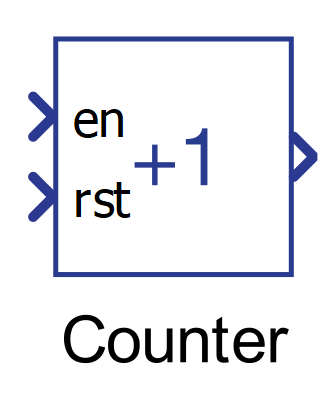
Component icon
Description
The Counter component increments the output signal by one every simulation step.
The output value is given by the expression:
out value = current state + 1
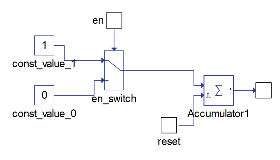
The counter component is a composite component and its implementation is illustrated in Figure 2.
Initial value
The Initial value, or the initial condition, specifies the Counter component’s starting value. The Initial value can be specified through the Initial value property.
The Initial value applies when the simulation is started and also when the reset signal is detected.
Enable
The Counter component will be active only when the enable signal is greater than 0.
Reset
Counter output can be externally reset using signals connected to the reset terminal. The value of the output signal is reset to the initial value.
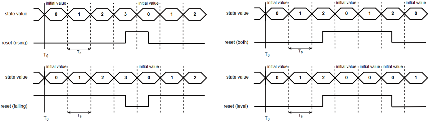
Choices for reset logic are:
- Rising edge – the state is reset if the rising edge is detected on the reset signal
- Falling edge – the state is reset if the falling edge is detected on the reset signal
- Either edge – the state is reset if either the rising or the falling edge is detected on the reset signal
- Level – the state value remains the same as the initial value as long as the reset signal is not 0
Figure below illustrates each reset option.
Ports
- Enable en (in)
- Supported types: uint, int, real
- Vector support: no
- Reset rst (in)
- Supported types: uint, int, real
- Vector support: no
- Out (out)
- Supported types: uint, int, real
- The output type is dictated by the State type property value
- Vector support: no
- Supported types: uint, int, real
Properties
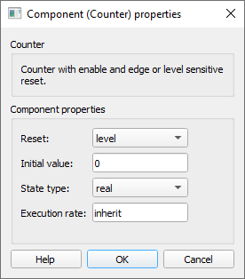
- Reset
- Select the state in which the output of the counter component is reset. The state can be reset on the rising edge ("rising"), the falling edge ("falling"), both the rising and the falling edges of the reset signal ("either"), or it can stay in the initial state as long as the value of the reset signal is not 0 ("level").
- Initial value
- Type in the initial value of the Counter component. This value is applied when the simulation is started and when the reset signal is active.
- State type
- Select the type of the output signal. The available options are: "real", "int", or "uint".
- Execution rate
- Type in the desired signal processing execution rate. This value must be compatible with other signal processing components of the same circuit: the value must be a multiple of the fastest execution rate in the circuit. There can be up to four different execution rates. To specify the execution rate, you can use either decimal (e.g. 0.001) or exponential values (e.g. 1e-3) in seconds. Alternatively, you can type in ‘inherit’ in which case the component will be assigned execution rate based on the execution rate of the components it is receiving input from.