Introduction | Meet the H-Bridges Team
H-Bridges, a student team from the University of Belgrade School of Electrical Engineering, Serbia, brings together students with a shared passion and a common goal. Under the mentorship of Assistant Professor Dr. Aleksandar Milić, in the Digital Drive Control Laboratory, every year, we participate in the world’s largest university competition in the field of innovative and energy-efficient solutions, the International Future Energy Challenge (IFEC), organized by IEEE. The competition gathers teams from some of the world’s most prestigious universities, where students develop and implement innovative technical solutions through year-long projects.
H-Bridges consists of students from all study programs at the University of Belgrade School of Electrical Engineering, organized into several sub-teams: hardware and PCB design, firmware and control, as well as fundraising and public relations. This structure encourages continuous knowledge transfer, peer learning, and strong collaboration between younger and more experienced students. One of the key values of H-Bridges is diversity, not only in terms of academic background, but also in perspectives, experience, and approaches to problem-solving. By bringing together students from different fields and years of study, the team creates an environment that supports innovation, creativity, and mutual growth.

Challenges | IFEC 2026 Technical Requirements
IFEC is an international student competition focused on advancing innovation, conservation, and the effective use of electric energy through hands-on engineering design. This year’s challenge is to design, build, and demonstrate an affordable, bidirectional, isolated on-board charger prototype that is safe, manufacturable, and high-performance.
The primary focus was placed on the technical performance of the system, particularly efficiency, power density, reliability, and bidirectional operation, while cost optimization was considered an additional evaluation criterion.
The system was required to operate with dual single-phase AC input voltage levels of 120 Vac (60 Hz) and 230 Vac (50 Hz), enabling compatibility with different grid standards and operating environments. The nominal output voltage was specified at 400 Vdc, with an operating range of approximately 300–450 Vdc to ensure stable operation under varying conditions.
The required power rating was 1 kW, with bidirectional power capability included to support both standard operation and light-load testing scenarios. Emphasis was placed on achieving high efficiency, with target values exceeding 92% at full load (1 kW) and 80% at 100 W. In parallel, the converter was expected to achieve a power density of 2 kW/l, including the cooling system and EMI filters, highlighting the need for a compact and highly optimized design.
The testing procedure was designed to be fully plug-and-play, without requiring additional interfaces or user interaction, simplifying validation and operation. During development and testing, bidirectional power supplies and resistive loads were employed to safely emulate operating conditions.
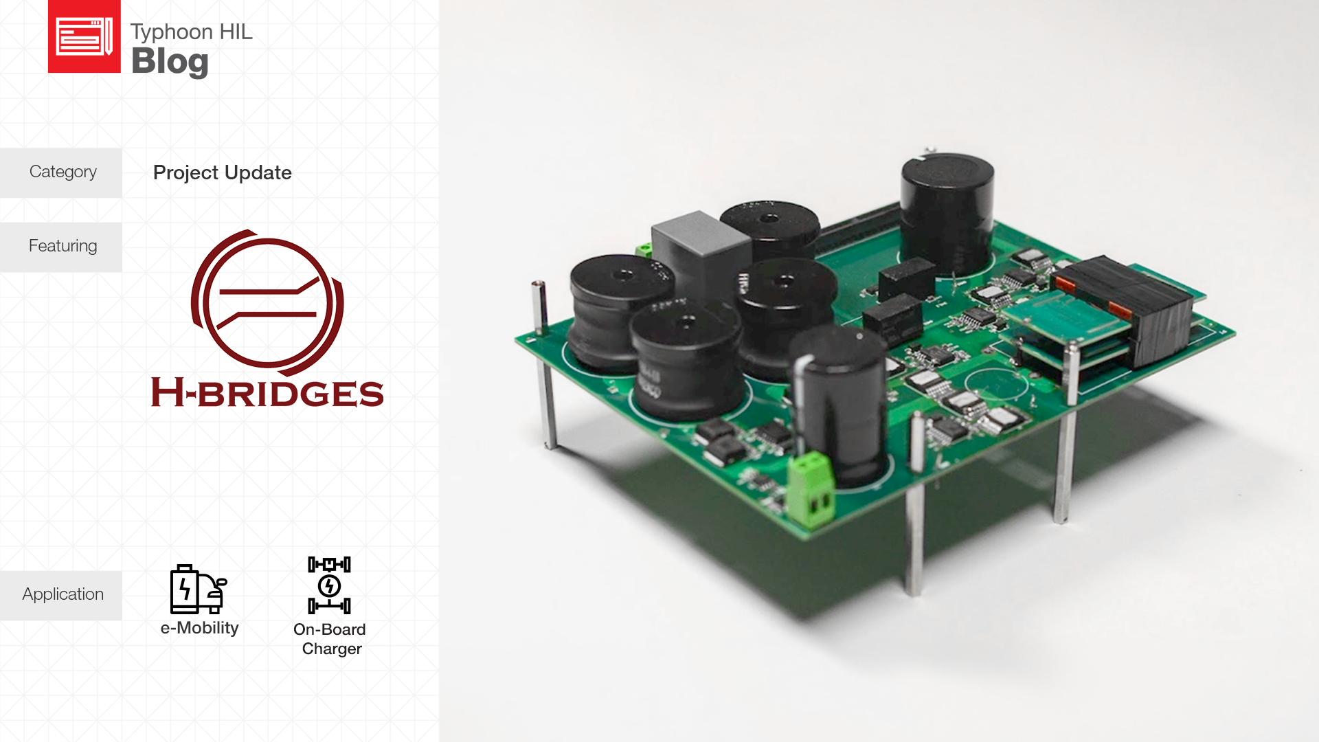
Solution | The Two-Stage Topology
Following an extensive literature review, analytical modeling, and simulation analysis, both single-stage and two-stage converter topologies demonstrated promising efficiency, power density, and cost performance. However, the two-stage approach was ultimately selected due to its simpler control implementation and greater flexibility in meeting the competition requirements.
To achieve the required total harmonic distortion (THD), power factor, efficiency, and bidirectional operation, a Boost power factor correction (PFC) stage was selected for the AC/DC conversion stage. For the isolated DC/DC stage, a Dual Active Bridge (DAB) topology was chosen due to its bidirectional capability, galvanic isolation, high efficiency and ability to support battery charging across different operating modes while maintaining high power density.
The system employs four auxiliary supply levels to ensure reliable powering of peripheral circuits. In addition, five sensors and isolated gate drivers are integrated to provide low-noise operation and stable control performance.
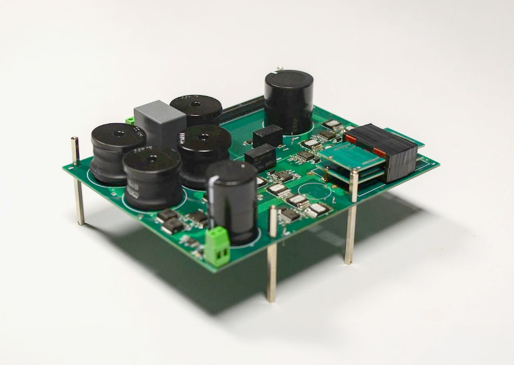
A detailed loss analysis of the filter components, switching devices, and DC-link capacitors was carried out to determine the optimal switching frequency of the PFC stage. Key design parameters influencing the DAB switching frequency were also evaluated, balancing efficiency and power density requirements. Magnetic component design included verification of design assumptions, flux distribution analysis, inductance calculation, and thermal evaluation to ensure reliable operation under targeted conditions.
After selecting the filter structure and corresponding parameters according to the previously defined criteria, modulation strategies were analyzed with a focus on THD performance. Simulation-based comparison showed that all considered modulation methods satisfied the required criteria; however, unipolar modulation was selected due to its return-to-zero characteristic and simpler implementation.
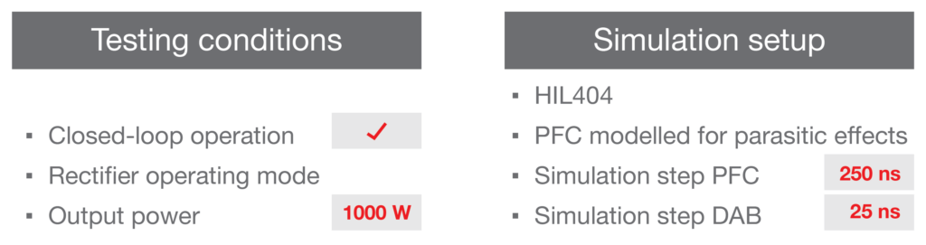
As part of our development process, we used the Typhoon HIL’s HIL404 real-time simulator to validate our two-stage On-Board Charger (OBC) topology under realistic operating conditions. The setup enabled us to thoroughly assess the PFC front-end reactions to grid disturbances, including voltage sags and frequency variations. For the DC-DC stage, we used the UltraCore technology to precisely simulate switching behavior and transient responses. Additionally, the setup provided accurate insight into the interaction between the two stages, significantly accelerating our testing and validation process.
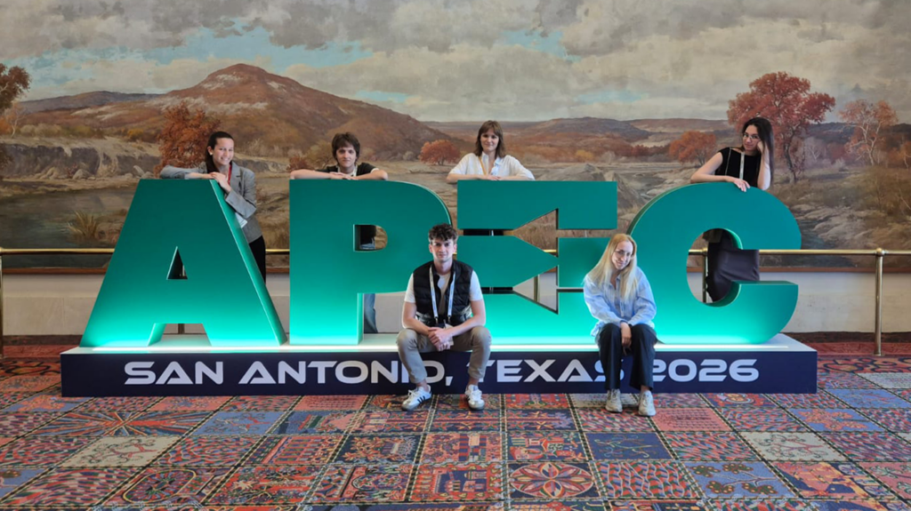
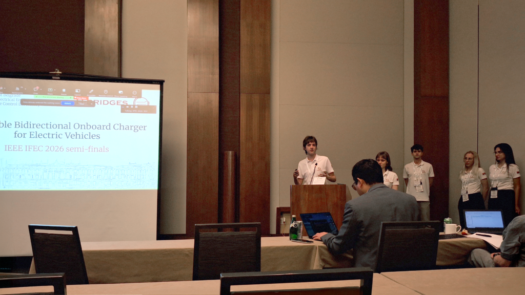
By the semifinal stage of the competition, the team had successfully achieved bidirectional operation on both converter stages at 1000 W output power, successfully validated the desired output voltage range for both stages, and maintained an operating temperature below 75°C during hardware testing. In parallel, the firmware development enabled closed-loop operation of both stages and successful integration of the complete state machine architecture. These results were demonstrated during the APEC 2026 conference in March, in San Antonio, TX. Following the conference, the system underwent a redesign phase focused on further optimization and preparation for the next stage of development.
HIL Benefits | The HIL 404 Real-Time Simulator
Using a HIL simulator significantly reduces the risk of equipment damage during development and testing, while also lowering overall development costs. By validating control software and system behavior in advance, the team can identify potential issues early in the development process and organize testing more efficiently. The simulator provides a safe and reliable environment for observing system behavior and verifying the correct operation of control algorithms before deployment on final hardware.
Over the years, the team has consistently achieved strong results in the simulation and validation stages of development. We believe that cooperation with Typhoon HIL and the use of the HIL404 device have played an important role in enabling a more reliable and efficient development process, contributing to the team’s success during competitions.