Wind Turbine
Description of the Wind Turbine model component in Schematic Editor, which emulates the mechanical and aerodynamic behavior of a wind turbine.
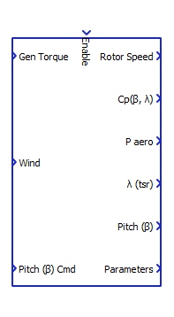
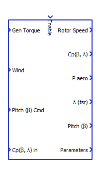
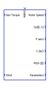
Component Icons
 |
 |
 |
Description
The Wind Turbine component contains a simplified model of the mechanical system and the aerodynamics of a wind turbine.
Taking the generator torque (Gen Torque, ), blade pitch angle command (Pitch β Cmd), and wind speed (Wind) as inputs, the wind turbine model provides rotor speed ( ), Power Coefficient (Cp(β, λ)), Aerodynamic Power (P aero), tip-speed ratio (λ (tsr)), and blade pitch angle (Pitch β) as operating data. An additional vectored output provides the wind turbine parameters. The Generator Speed ( ) can be calculated multiplying the rotor speed ( ) by the gearbox ratio.
| Parameter | Description |
|---|---|
| P aero | Wind Turbine Aerodynamic Power [W] |
| R | Rotor radius [m] |
| ρ | Air density [kg/m^3] |
| Rotor Inertia [kg.m^2] | |
| Rotor speed [rad/s] | |
| Generator Torque [N.m] | |
| Rotor Torque [N.m] | |
| Cp(β, λ) | Coefficient of power |
| λ | tip speed ratio |
| β | Blade pitch angle [degree] |
| Gearbox ratio (ng/nr) | |
| Wind Speed [m/s] | |
| Blade model frequency [rad/s] | |
| Blade model damping coefficient [N.s/m] | |
| Tip-speed-ratio scalar gain |
The wind turbine model structure is shown in Figure 1.
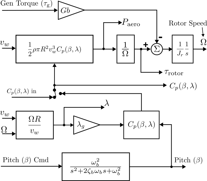
Considering that these are simplified models, the Wind Turbine Power curve will be slightly different from that obtained in a specialized CAE, like NREL OpenFAST, and the model is intended to be used in the normal operating range of wind speed and rotor speed. Therefore, the required computational effort is significantly lower than required for a detailed model simulation.
Ports
- Enable (in)
- Input for enabling and disabling the wind turbine component.
- Supported types: integer.
- Vector support: no.
- Input for enabling and disabling the wind turbine component.
- Gen Torque (in)
- Generator Torque input, referred to the generator speed, in N.m/s.
- Supported types: real.
- Vector support: no.
- Generator Torque input, referred to the generator speed, in N.m/s.
- Pitch (β) Cmd (in)
- Input signal of blade pitch command, in degrees. Allowed range from 0 to 80 degrees.
Typically, this is the signal coming from the pitch controller.
- Supported types: real.
- Vector support: no.
- Input signal of blade pitch command, in degrees. Allowed range from 0 to 80 degrees.
Typically, this is the signal coming from the pitch controller.
- Wind (in)
- Wind speed
input signal, in m/s.
- Supported types: real.
- Vector support: no.
- Wind speed
input signal, in m/s.
- Cp(β, λ) in (in)
- Power Coefficient input, this is only active when "External" is selected for the
Cp(β, λ) curve.
- Supported types: real.
- Vector support: no.
- Power Coefficient input, this is only active when "External" is selected for the
Cp(β, λ) curve.
- Rotor Speed (out)
- Output signal of rotor speed, in RPM.
- Supported types: real.
- Vector support: no.
- Output signal of rotor speed, in RPM.
- Cp(β, λ) (out)
- Rotor Power coefficient output.
- Supported types: real.
- Vector support: no.
- Rotor Power coefficient output.
- P aero (out)
- Mechanical Power (W) output signal. This corresponds to the aerodynamical power
captured from the wind, available on the rotor axis.
- Supported types: real.
- Vector support: no.
- Mechanical Power (W) output signal. This corresponds to the aerodynamical power
captured from the wind, available on the rotor axis.
- λ (tsr) (out)
- Tip-speed-ratio, calculated as the blade tip angular speed.
- Supported types: real.
- Vector support: no.
- Tip-speed-ratio, calculated as the blade tip angular speed.
- Pitch (β) (out)
- The actual blade pitch angle in degrees at the dynamic model output. If the input
Pitch (β) Cmd is not used, the Pitch (β) output will have constant zero values.
- Supported types: real.
- Vector support: no.
- The actual blade pitch angle in degrees at the dynamic model output. If the input
Pitch (β) Cmd is not used, the Pitch (β) output will have constant zero values.
- Parameters (out)
- Vector output containing the wind turbine parameters.
- Supported types: real.
- Vector support: yes.
- The available parameters are listed below, and can be accessed using a Bus Split
component:
- Parameters[0]: wind speed cut-in (m/s).
- Parameters[1]: wind speed rated (m/s).
- Parameters[2]: wind speed cut-out (m/s).
- Parameters[3]: Rotor Speed (RPM) for start generating power.
- Parameters[4]: Rated Rotor Speed (RPM).
- Parameters[5]: α constant for MPPT Torque control, .
- Parameters[6]: Gearbox ratio.
- Parameters[7]: Rated Generator Torque (N.m).
- Parameters[8]: Wind turbine rated power (MW).
- Vector output containing the wind turbine parameters.
Properties
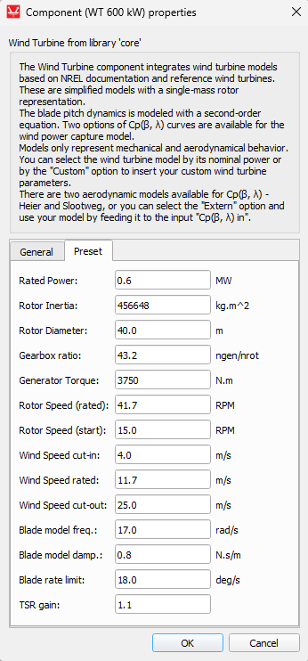
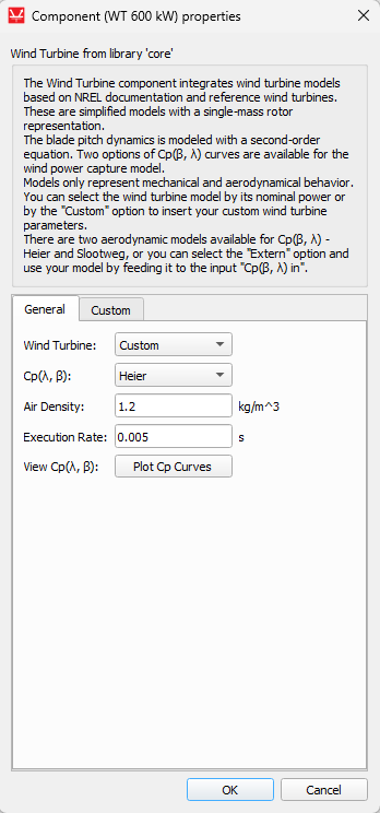
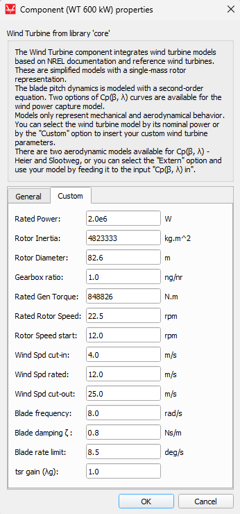
The Wind Turbine component interface features two or three tabs based on its configuration. The General tab houses primary options, while the Custom tab allows for comprehensive configuration of all wind turbine model parameters. Custom tab fields are editable only when a Custom Wind Turbine is selected on the General tab. The Parameters tab displays the currently selected wind turbine parameters, and it is not visible when a Custom Wind Turbine is selected.
 |
 |
 |
 |
- Wind Turbine
- Select the wind turbine model by choosing its nominal power or Custom option.
- Cp(β, λ)
- Choose the Cp(β, λ) curve: Slootweg [1] or Heier [2].
- Air Density [kg/m^3]
- Specify the air density.
- Execution Rate
- Specify the simulation step (seconds) for the wind turbine component. As the mechanical/aerodynamic model contains only slow dynamics, large values like 0.005 s can be used.
- View Cp(β, λ)
- The "Plot Cp Curves" button plots the selected type of Cp(β, λ) curve for the selected wind turbine (disregarding the gain).
- Rated Power [W]
- The Wind Turbine nominal Power. It must be configured in the range of 1.0 kW to 100 MW.
- Rotor Diameter [m]
- Diameter of the Wind Turbine rotor [m]. It must be equal or greater than 1.0 m.
- Rated Gen Torque [N.m]
- Generator Torque when the wind turbine is generating rated power. It must be a positive value, equal or greater than 2.0 N.m.
- Rated Rotor Speed [RPM]
- Rotor speed at which the turbine generates rated power. It must be equal or greater 0.5 RPM.
- Rotor Speed start [RPM]
- Rotor Speed when the wind turbine starts generating power. It must be greater than 0.2 RPM and smaller than the Rated Rotor Speed.
- Gearbox ratio
- The ratio between generator speed and rotor speed (ng/nr).
- Wind Spd cut-in [m/s]
- Wind Speed when the Wind Turbine turns on. It must be greater than 1.5 m/s.
- Wind Spd rated [m/s]
- Wind Turbine rated wind speed. It must be in the range of 6.0 to 18.0 m/s.
- Wind Spd cut-out [m/s]
- Wind Turbine cut-out wind speed. It must be greater than the rated wind speed.
- Blade frequency [rad/s]
- Blade model frequency. It must be in the range of 0.5 to 50 rad/s.
- Blade damping [Ns/m]
- Blade model damping coefficient. It must be in the range of 0.1 to 3.0 Ns/m.
- Blade rate limit [deg/s]
- Blade model rate limit. It must be in the range of 0.5 to 50 degrees per second.
- tsr gain (
)
- Tip-speed-ratio scalar gain to best fit Cp(β, λ) curves. It must be in the range of 0.5 to 3.0.
- Execution rate
- Type in the desired signal processing execution rate. This value must be compatible with other signal processing components of the same circuit: the value must be a multiple of the fastest execution rate in the circuit. There can be up to four different execution rates. To specify the execution rate, you can use either decimal (e.g. 0.001) or exponential values (e.g. 1e-3) in seconds. Alternatively, you can type in ‘inherit’ in which case the component will be assigned execution rate based on the execution rate of the components it is receiving input from.
References
[1] J. G. Slootweg, S. W. H. de Haan, H. Polinder and W. L. Kling, "General model for representing variable speed wind turbines in power system dynamics simulations," in IEEE Transactions on Power Systems, vol. 18, no. 1, pp. 144-151, Feb. 2003, doi: 10.1109/TPWRS.2002.807113.
[2] Heier, S. (2014). Grid integration of wind energy (3rd ed.). doi:10.1002/9781118703274.