IEEE DC1A Exciter
Description of the IEEE DC1A Exciter component in Schematic Editor, which provides generic excitation for a synchronous machine and regulates its terminal voltage in generating mode.
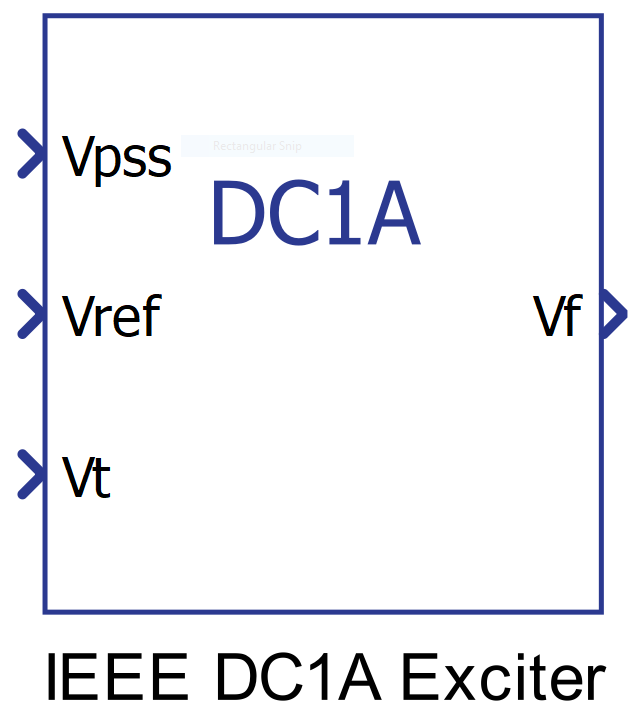
Component Icon
Note: This component requires an active Grid Resources functional library license for real-time simulation.
Description
The DC1A is the most widely implemented exciter in industry and can often be used as a generic exciter when more detailed data is not available. It represents a class of exciters with a field-controlled DC commutator and a continuously-acting voltage regulator. A block diagram of the IEEE DC1A exciter without overexcitation and underexcitation limiters is shown in Figure 2 where the voltage regulator is represented by constants Ka and Ta . This class of exciter can be either self or separately excited. In the case of separate excitation the constant Ke should be set to 0.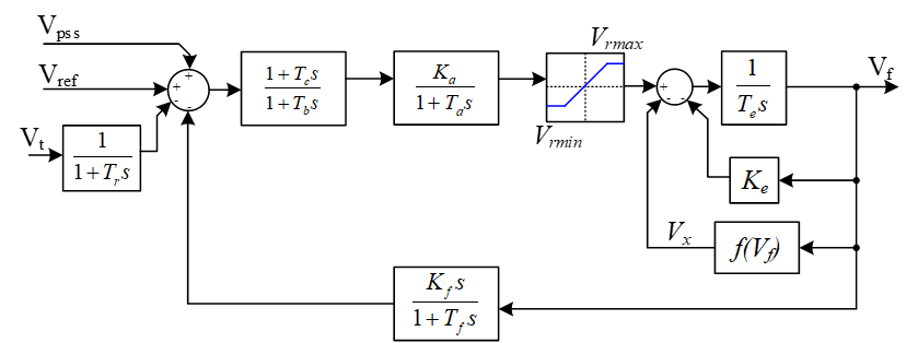
The exciter core saturation is not modeled. This is equivalent to setting Vx to 0 in the figure above.
Ports
- Vpss (in)
- Connect this input to a power system stabilizer to provide additional
stabilization of power system oscillations.
- Supported types: uint, int and real.
- Vector support: no.
- Connect this input to a power system stabilizer to provide additional
stabilization of power system oscillations.
- Vref (in)
- The desired value, in pu, of the stator terminal voltage.
- Supported types: uint, int and real.
- Vector support: no.
- The desired value, in pu, of the stator terminal voltage.
- Vt (in)
- Output from the terminal voltage transducer and load compensator model
described by this model as standard states.
- Supported types: uint, int and real.
- Vector support: no.
- Output from the terminal voltage transducer and load compensator model
described by this model as standard states.
- Vf (out)
- Field voltage, in pu, for a Synchronous Machine block
- Supported types: real.
- Vector support: no.
- Field voltage, in pu, for a Synchronous Machine block
Properties
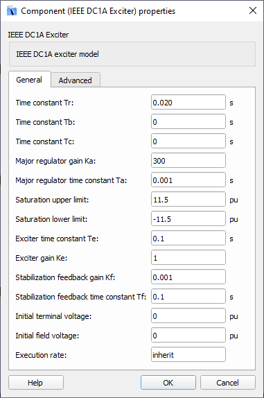
- Time constant Tr
- Type in the terminal voltage transducer time constant. Set to 0 if terminal voltage measurement already accounts for measurement time delay.
- Time constants Tb and Tc
- Type in the time constants Tb (lag time) and Tc (lead time) that may be used to model equivalent time constants inherent in the voltage regulator. However, these time constants are frequently small enough to be neglected.
- Major regulator gain Ka and time constant Ta
- Type in the values of the major time constant, Ta, and the gain, Ka, represented by a first-order system associated with the voltage regulator.
- Saturation upper and lower limits
- Type in the values for the saturation limits of the voltage regulator in pu.
- Exciter gain Ke and time constant Te
- Type in the values of the time constant, Te, and the gain, Ke, represented by a first-order system associated with the exciter.
- Stabilization feedback gain Kf and time constant Tf
- Type in the values of the time constant, Tf, and the gain, Kf, represented by a first-order system associated with the stabilization feedback which uses a signal derived from field voltage in order to provide excitation system stabilization.
- Initial terminal voltage and Initial field voltage
- Type in the initial values of terminal voltage and field voltage, in pu.
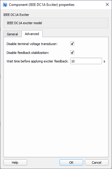
- Disable terminal voltage transducer
- Select this property for disabling the transducer for terminal voltage.
- Disable feedback stabilization
- Select this property for disabling the loop for feedback stabilization.
- Wait time before applying exciter feedback
- Type in the simulation time (in seconds) for applying the exciter feedback.
- Execution rate
- Type in the desired signal processing execution rate. This value must be compatible with other signal processing components of the same circuit: the value must be a multiple of the fastest execution rate in the circuit. There can be up to four different execution rates. To specify the execution rate, you can use either decimal (e.g. 0.001) or exponential values (e.g. 1e-3) in seconds. Alternatively, you can type in ‘inherit’ in which case the component will be assigned execution rate based on the execution rate of the components it is receiving input from.